Abstract
Increasingly researchers are looking to bring together perspectives across multiple scales, or to combine insights from different techniques, for the same region of interest. To this end, correlative microscopy has already yielded substantial new insights in two dimensions (2D). Here we develop correlative tomography where the correlative task is somewhat more challenging because the volume of interest is typically hidden beneath the sample surface. We have threaded together x-ray computed tomography, serial section FIB-SEM tomography, electron backscatter diffraction and finally TEM elemental analysis all for the same 3D region. This has allowed observation of the competition between pitting corrosion and intergranular corrosion at multiple scales revealing the structural hierarchy, crystallography and chemistry of veiled corrosion pits in stainless steel. With automated correlative workflows and co-visualization of the multi-scale or multi-modal datasets the technique promises to provide insights across biological, geological and materials science that are impossible using either individual or multiple uncorrelated techniques.
🔬 Techniques
🔭 Microscopes
🏭 Microscope Brands
💻 Software Details
🏛️ Research Organizations (ROR)
Affiliated research institutions:
📋 Methods
A commercial grade 316H austenitic stainless steel sample in the solution annealed condition with a grain size of 37 ± 4 μm (excluding twin grain boundaries) was used for manufacturing cylindrical tensile sample, with a gauge length of 20 mm and gauge diameter of 2.5 mm. A sensitization heat-treatment at 650°C for 24 hours in argon atmosphere was carried out to produce a microstructure susceptible to intergranular corrosion. The gauge was ground with SiC paper to a 2500 grit finish.
Electrochemical corrosion testing using time-lapse X-ray computer tomography
(CT) was employed to follow the evolution of pitting corrosion in situ. A 25 mm (outer) diameter cylindrical Perspex tube was used as the environmental cell for the in-situ electrochemical experiments. The sample was centred in the environmental cell, connected to a potentiostat, and the set-up then mounted upon the rotation stage of the X-ray scanner. Electrochemical tests were carried out at room temperature using an IVIUM Compactstat and IivumSoft acquisition software. The sample acted as working electrode, with a platinum counter electrode, and a saturated Ag/AgCl miniature reference electrode. A 0.1 molar NaCl solution was used for all tests with the open circuit potential (OCP) recorded for 2 to 10 minutes until the potential was stable, followed by potentio-dynamic polarization scans using a potential step-size of 1 mV/s.
Time lapse medium resolution
X-ray tomography was undertaken at medium resolution (3.4 μm) in a lab-based Xradia Versa instrument using 150 kV X-ray energy at 4x optical magnification with an exposure time of 5 seconds and a total of 801 projections. Data were reconstructed using a Feldkamp-Davis-Kress (FDK) reconstruction. A first assessment of the sample was carried out after polarization from −50 mV vs. OCP to +350 mV, but no pitting corrosion was observed in the CT data (scan 1). The second polarization step was conducted from −50 mV vs. OCP to +580 mV followed by an assessment using X-ray CT to see where corrosion had initiated (scan 2). A third CT scan was then carried out after polarizing the sample from −50 mV vs. OCP to +350 mV, using a step size of 4 mVs −1 (scan 3). After each potentio-dynamic polarization, the tensile sample was disconnected from the potentiostat to allow unconstrained rotations for CT assessment but with the sample remaining in situ in the NaCl solution the whole time. Each CT experiment scan was conducted using the same imaging conditions. High resolution X-ray CT After the corrosion experiments, high resolution X-ray CT scanning was also conducted on an Xradia Versa X-ray microscope on a 1.5 mm thick diametral slice from the original 2.5 mm diameter volume capturing the corrosion pit of interest. From this volume it was possible to achieve high resolution (0.8 μm 3 voxel size) resolution using region of interest imaging with superior contrast compared the overview scan of the entire sample, which was limited by both the field of view and the thickness of the steel. The imaging conditions used were 140 kV at 4x optical magnification with an exposure time of 15 seconds per projection and a total of 3201 projections. Data were reconstructed using an FDK reconstruction. Serial section FIB-SEM: was conducted on a FEI Nova Nanolab Dual Beam microscope using the automated Slice and View TM software utilizing both the electron and gallium ion beams, with detection via secondary electrons using the Everhart-Thornley detector (ETD) at 5 kV accelerating voltage and 1 nA beam current. A standard procedure for the creation of the cross sections was followed once the RoI had been identified. Side trenches were also excavated to alleviate re-deposition build up. The serial sections of nominal 50 nm thickness were prepared with the FIB using 1 nA current at 30 kV. The imaging pixel size was 87 nm 2 . A total of 60 slices were recorded taking ~8 hours. For an overview of working with the FIB for specimen preparation and serial sectioning please see e.g. 36 37 and references therein.
Show full methods section
A commercial grade 316H austenitic stainless steel sample in the solution annealed condition with a grain size of 37 ± 4 μm (excluding twin grain boundaries) was used for manufacturing cylindrical tensile sample, with a gauge length of 20 mm and gauge diameter of 2.5 mm. A sensitization heat-treatment at 650°C for 24 hours in argon atmosphere was carried out to produce a microstructure susceptible to intergranular corrosion. The gauge was ground with SiC paper to a 2500 grit finish.
Electrochemical corrosion testing using time-lapse X-ray computer tomography
(CT) was employed to follow the evolution of pitting corrosion in situ. A 25 mm (outer) diameter cylindrical Perspex tube was used as the environmental cell for the in-situ electrochemical experiments. The sample was centred in the environmental cell, connected to a potentiostat, and the set-up then mounted upon the rotation stage of the X-ray scanner. Electrochemical tests were carried out at room temperature using an IVIUM Compactstat and IivumSoft acquisition software. The sample acted as working electrode, with a platinum counter electrode, and a saturated Ag/AgCl miniature reference electrode. A 0.1 molar NaCl solution was used for all tests with the open circuit potential (OCP) recorded for 2 to 10 minutes until the potential was stable, followed by potentio-dynamic polarization scans using a potential step-size of 1 mV/s.
Time lapse medium resolution
X-ray tomography was undertaken at medium resolution (3.4 μm) in a lab-based Xradia Versa instrument using 150 kV X-ray energy at 4x optical magnification with an exposure time of 5 seconds and a total of 801 projections. Data were reconstructed using a Feldkamp-Davis-Kress (FDK) reconstruction. A first assessment of the sample was carried out after polarization from −50 mV vs. OCP to +350 mV, but no pitting corrosion was observed in the CT data (scan 1). The second polarization step was conducted from −50 mV vs. OCP to +580 mV followed by an assessment using X-ray CT to see where corrosion had initiated (scan 2). A third CT scan was then carried out after polarizing the sample from −50 mV vs. OCP to +350 mV, using a step size of 4 mVs −1 (scan 3). After each potentio-dynamic polarization, the tensile sample was disconnected from the potentiostat to allow unconstrained rotations for CT assessment but with the sample remaining in situ in the NaCl solution the whole time. Each CT experiment scan was conducted using the same imaging conditions. High resolution X-ray CT After the corrosion experiments, high resolution X-ray CT scanning was also conducted on an Xradia Versa X-ray microscope on a 1.5 mm thick diametral slice from the original 2.5 mm diameter volume capturing the corrosion pit of interest. From this volume it was possible to achieve high resolution (0.8 μm 3 voxel size) resolution using region of interest imaging with superior contrast compared the overview scan of the entire sample, which was limited by both the field of view and the thickness of the steel. The imaging conditions used were 140 kV at 4x optical magnification with an exposure time of 15 seconds per projection and a total of 3201 projections. Data were reconstructed using an FDK reconstruction. Serial section FIB-SEM: was conducted on a FEI Nova Nanolab Dual Beam microscope using the automated Slice and View TM software utilizing both the electron and gallium ion beams, with detection via secondary electrons using the Everhart-Thornley detector (ETD) at 5 kV accelerating voltage and 1 nA beam current. A standard procedure for the creation of the cross sections was followed once the RoI had been identified. Side trenches were also excavated to alleviate re-deposition build up. The serial sections of nominal 50 nm thickness were prepared with the FIB using 1 nA current at 30 kV. The imaging pixel size was 87 nm 2 . A total of 60 slices were recorded taking ~8 hours. For an overview of working with the FIB for specimen preparation and serial sectioning please see e.g. 36 37 and references therein.
Crystallographic and Chemical analysis
Using the same FEI Nova Nanolab FIB-SEM a TEM lamella sample was prepared adjacent to the final slice of the Slice and View TM volume and extracted in situ using an Omniprobe micromanipulator. The lamella was then attached to a copper TEM grid and welded in place by depositing Pt at the interface. This sample was first analysed using transmission EBSD analysis using 30 kV accelerating voltage, 3.2 nA probe current and 2 mm working distance with a 50 nm step size. The data were gathered using the Oxford Instruments NordlysNano detector and AZtecHKL software version 2.0. STEM and EDX spectrum imaging were performed using a probe-side aberration-corrected FEI Titan G2 80–200 S/TEM operated at 200 kV. STEM images were collected using a convergence angle of 18 mrad and a high angle annular dark-field (HAADF) detector with an inner angle of 55 mrad. EDX compositional analysis was performed using the Super-X detector configuration (4 × 30 mm 2 SDDs) with a solid angle of ~0.7 srad and a beam current of ~0.6 nA. Spectrum images were acquired with non-standard times, until total counts were deemed sufficient, with a dwell time of 30 μs per pixel. For display purposes, all spectrum images were processed using a 3-pixel smoothing window in the Bruker Esprit software.
3D visualization
All of the reconstructed data were analysed and visualized in 3D using FEI Avizo software.
Supplementary Material Supplementary Information Correlative Tomography Supplementary Information Movie S3 Supplementary Information Movie S8
📊 Figures
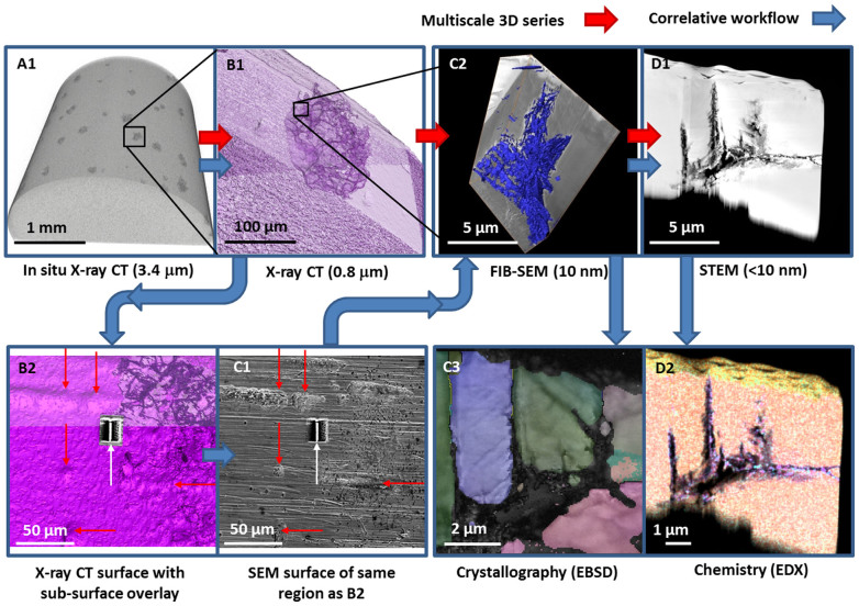
Figure 1
Correlative tomography workflow applied to study the nucleation and growth of pits in sensitized stainless steel linking together (A) medium and (B) high resolution X-ray CT with (C) serial sectioning...
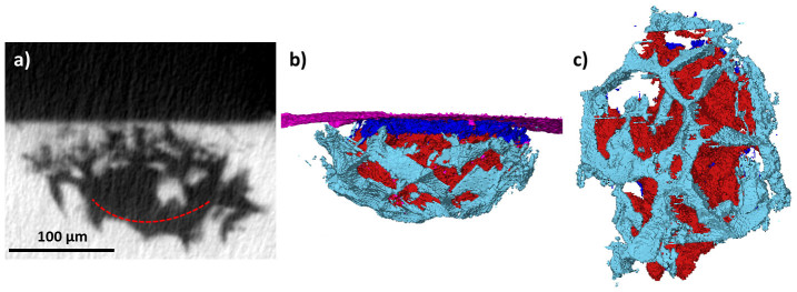
Figure 2
a) Virtual slice through the 3D image collected at high resolution (0.8u2005u03bcm voxel size) for the selected pit (approximate extent marked by red dashed line), b) side and c) underside 3D segmente...
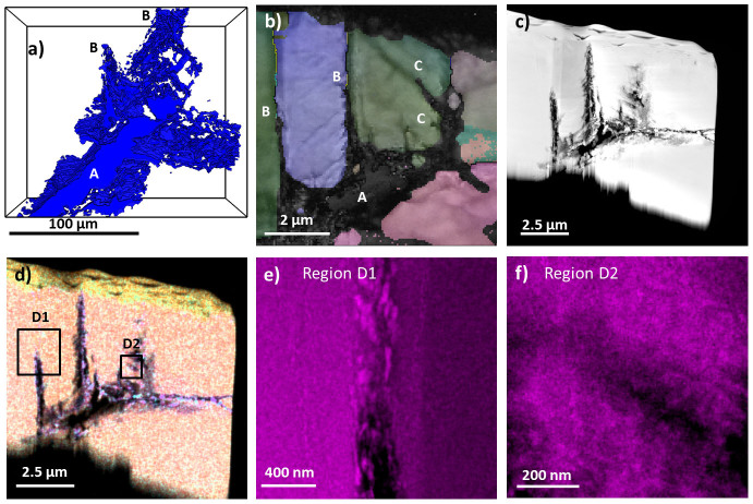
Figure 3
a) 3D visualization of a region of the crack front obtained by serial section FIB-SEM with the grain boundary (A) and CSL boundaries (B) indicated. b) EBSD map from final slice adjacent to the serial ...
Figure images are served from the NIH/NLM PubMed Central Open Access Subset or Europe PMC; copyright remains with the publishers and authors.
💬 Discussion
0 commentsNo comments yet. Be the first to start a discussion!
Leave a Comment