Abstract
Abstract Innexins, a large protein family comprising invertebrate gap junction channels, play an essential role in nervous system development and electrical synapse formation. Here we report the cryo-electron microscopy structures of Caenorhabditis elegans innexin-6 (INX-6) gap junction channels at atomic resolution. We find that the arrangements of the transmembrane helices and extracellular loops of the INX-6 monomeric structure are highly similar to those of connexin-26 (Cx26), despite the lack of significant sequence similarity. The INX-6 gap junction channel comprises hexadecameric subunits but reveals the N-terminal pore funnel, consistent with Cx26. The helix-rich cytoplasmic loop and C-terminus are intercalated one-by-one through an octameric hemichannel, forming a dome-like entrance that interacts with N-terminal loops in the pore. These observations suggest that the INX-6 cytoplasmic domains are cooperatively associated with the N-terminal funnel conformation, and an essential linkage of the N-terminal with channel activity is presumably preserved across gap junction families.
🔬 Techniques
🧬 Organisms
✨ Fluorophores
🏭 Microscope Brands
🧪 Reagent Suppliers
💻 Software Details
💾 Data Repositories
🏛️ Research Organizations (ROR)
Affiliated research institutions:
📋 Methods
Preparation of INX-6 for cryo-EM using GraDeR Wild-type
INX-6 with GFP plus an 8 × -histidine tag at the C-terminus was isolated and purified from Sf9 cells as described previously 15 22 . In summary, Sf9 cells cultured at 27 °C were infected with the recombinant virus and harvested after infection for 30∼40 h. The following processes were all performed at 4 °C. The harvested cells were sonicated for 1.5 min in buffer containing 10 mM Tris (pH 7.5), 150 mM NaCl and 1 mM phenylmethylsulfonyl fluoride, and centrifuged at 22,100 g for 25 min. The isolated membranes were solubilized in buffer containing 10 mM Tris (pH 7.5), 150 mM NaCl and 2% n-dodecyl-β- D -maltopyranoside (Anatrace) for 30 min. The mixture was centrifuged at 13,000 g for 10 min, and the supernatant was bound to Ni-nitrilotriacetic acid agarose (Qiagen). The protein bound resins were washed with buffer containing 10 mM Tris (pH 7.5), 150 mM NaCl, 10 mM L -histidine and 0.1% digitonin (Wako), and eluted with 300 mM L -histidine. After digesting the C-terminal tag followed by gel filtration with buffer (10 mM Tris (pH 7.5), 500 mM NaCl and 0.1% octyl glucose neopentyl glycol; Anatrace), the fractions containing the INX-6 channels were subjected to GraDeR 21 with minor modifications. LMNG (lauryl maltose neopentyl glycol, Anatrace) was added to the gel filtration fraction of INX-6 at a final concentration of 0.02%. Two different density gradient buffers were prepared. Buffer A for the top layer contained 10 mM Tris (pH 7.5), 500 mM NaCl, 5% glycerol and 0.003% LMNG. Buffer B for the bottom layer was LMNG-free, and contained 10 mM Tris (pH 7.5), 500 mM NaCl and 25% glycerol. Buffers A and B were stacked in centrifuge tubes for a Beckman SW41 at a total volume of ∼12 ml. The gradient was generated with a Gradient Master 108 (Biocomp Instruments) using the program for a long cap and glycerol 5%/25% (w/w), with the following parameters: 45 s (time), 86° (angle) and 25 rpm (speed). The INX-6 protein solution (100∼500 μl in 0.02% LMNG) was carefully loaded onto the top of the gradient buffer without disturbing the gradient solution. Centrifugation was carried out at 35,000 rpm (209,678 g ) for 12 h at 4 °C. The centrifuged solution was fractionated from bottom to top using a peristaltic pump (Perista Pump, ATTO), and the fractions were subjected to fluorescence-detection size-exclusion chromatography 34 to determine the sedimented position. To remove the glycerol, the fractions containing INX-6 were assembled in a Spectra/pore 7 dialysis tube (molecular weight cutoff: 25,000, Spectrum Laboratories), and dialysed against 1 l of dialysis buffer (10 mM Tris (pH 7.5) and 500 mM NaCl) for 1 h at 4 °C. The dialysed sample was negatively stained with 2% uranyl acetate and observed on a JEM-1010 (JEOL) operated at 100 kV. The INX-6 channels were concentrated to 2∼3 mg ml −1 using a concentrating device with a molecular weight cutoff of 30,000.
Show full methods section
Preparation of INX-6 for cryo-EM using GraDeR Wild-type
INX-6 with GFP plus an 8 × -histidine tag at the C-terminus was isolated and purified from Sf9 cells as described previously 15 22 . In summary, Sf9 cells cultured at 27 °C were infected with the recombinant virus and harvested after infection for 30∼40 h. The following processes were all performed at 4 °C. The harvested cells were sonicated for 1.5 min in buffer containing 10 mM Tris (pH 7.5), 150 mM NaCl and 1 mM phenylmethylsulfonyl fluoride, and centrifuged at 22,100 g for 25 min. The isolated membranes were solubilized in buffer containing 10 mM Tris (pH 7.5), 150 mM NaCl and 2% n-dodecyl-β- D -maltopyranoside (Anatrace) for 30 min. The mixture was centrifuged at 13,000 g for 10 min, and the supernatant was bound to Ni-nitrilotriacetic acid agarose (Qiagen). The protein bound resins were washed with buffer containing 10 mM Tris (pH 7.5), 150 mM NaCl, 10 mM L -histidine and 0.1% digitonin (Wako), and eluted with 300 mM L -histidine. After digesting the C-terminal tag followed by gel filtration with buffer (10 mM Tris (pH 7.5), 500 mM NaCl and 0.1% octyl glucose neopentyl glycol; Anatrace), the fractions containing the INX-6 channels were subjected to GraDeR 21 with minor modifications. LMNG (lauryl maltose neopentyl glycol, Anatrace) was added to the gel filtration fraction of INX-6 at a final concentration of 0.02%. Two different density gradient buffers were prepared. Buffer A for the top layer contained 10 mM Tris (pH 7.5), 500 mM NaCl, 5% glycerol and 0.003% LMNG. Buffer B for the bottom layer was LMNG-free, and contained 10 mM Tris (pH 7.5), 500 mM NaCl and 25% glycerol. Buffers A and B were stacked in centrifuge tubes for a Beckman SW41 at a total volume of ∼12 ml. The gradient was generated with a Gradient Master 108 (Biocomp Instruments) using the program for a long cap and glycerol 5%/25% (w/w), with the following parameters: 45 s (time), 86° (angle) and 25 rpm (speed). The INX-6 protein solution (100∼500 μl in 0.02% LMNG) was carefully loaded onto the top of the gradient buffer without disturbing the gradient solution. Centrifugation was carried out at 35,000 rpm (209,678 g ) for 12 h at 4 °C. The centrifuged solution was fractionated from bottom to top using a peristaltic pump (Perista Pump, ATTO), and the fractions were subjected to fluorescence-detection size-exclusion chromatography 34 to determine the sedimented position. To remove the glycerol, the fractions containing INX-6 were assembled in a Spectra/pore 7 dialysis tube (molecular weight cutoff: 25,000, Spectrum Laboratories), and dialysed against 1 l of dialysis buffer (10 mM Tris (pH 7.5) and 500 mM NaCl) for 1 h at 4 °C. The dialysed sample was negatively stained with 2% uranyl acetate and observed on a JEM-1010 (JEOL) operated at 100 kV. The INX-6 channels were concentrated to 2∼3 mg ml −1 using a concentrating device with a molecular weight cutoff of 30,000.
Cryo-EM data acquisition and image processing
For cryo-EM, pre-irradiated 200 mesh Quantifoil R2/2 molybdenum grids were glow-discharged and 1∼2 μl of INX-6 channels was placed onto the grid. Excess solution was blotted with a Vitrobot Mark IV (FEI) followed by plunge freezing into liquid ethane. The blotting parameters were as follows: blotting force 1∼3, blotting time 15∼20 s and 100% humidity at 22 °C. Data collection was performed on a JEM-3000SFF (JEOL) electron microscope at 300 kV with a field emission gun and a magnification of × 40,600. The specimen stage temperature was maintained at approximately 80-100 K. The images were recorded on a K2 summit direct electron detector camera (Gatan) operated in a super-resolution mode (7,676 × 7,420 pixels) with a pixel size of 0.616 Å at the specimen level. The dose rate was limited to 10.8 e − per physical pixel per second, corresponding to 7.1 e − per Å 2 at the specimen. The recording time was 7.2 s after a 0.7-s pre-dose delay, resulting in a total exposure time of 7.9 s and an accumulated dose of 56 e − per Å 2 . Each image includes 24 fractioned frames and one frame corresponds to 0.3-s exposure. The defocus ranged from −0.8 to −2.4 μm. For image processing, the dose fractioned image stacks were binned 2 × 2 by Fourier cropping, resulting in 3,838 × 3,710 pixels with a pixel size of 1.232 Å. The stacked frames were subjected to motion correction with MotionCorr 35 . CTF determination was performed using CTFFIND3 (ref. 36 ). EMAN2 (ref. 37 ) was used for particle picking and making the initial three-dimensional model. For the INX-6 hemichannel, 1,053 images were processed. In all, 341,585 particles were selected automatically on full-dose (56 e − per Å 2 ) images and extracted from first 14 frame-projected images (35 e − per Å 2 ) with a box size of 160 × 160 pixels. The particle set along with an initial three-dimensional model were passed to RELION 38 to calculate the three-dimensional classification, refinement and post-processing. Three-dimensional classification with C1 symmetry produced five classes. ‘Class 1' which showed the finest features of a docked hemichannel structure derived from 74,398 particles and ‘class 3' which contained 77,697 particles showing the features of an undocked hemichannel were independently subjected to the next iterative refinement with C8 symmetry. The three-dimensional refinement of ‘class 3' reached 7.3 Å resolution with the angular distribution biased toward top views ( Supplementary Fig. 2d ). The subsequent two-dimensional classification allowed us to select only side view particles from ‘class 3'. However, the selected 6,401 particles produced a 6.0 Å resolution map ( Supplementary Fig. 2d ), which was not included in this work due to the low resolution. Once the refinement using the ‘class 1' particles was converged, the particle set was replaced with the subset of the first eight frames (21 e − per Å 2 ) and refinement was restarted again until convergence. These data were used for post-processing on RELION to obtain the final three-dimensional reconstruction. For the INX-6 gap junction channel, we used 717 images that were part of the same data set for hemichannel analysis. Because auto particle picking does not work well for gap junction channels, manual picking was mainly used in combination with semi-auto picking in a compensative manner. 35,608 INX-6 gap junction channel particles were extracted from images of the 35 e − per Å 2 dose with a box size of 200 × 200 pixels, and an initial three-dimensional model was obtained on EMAN2. In the RELION process, all extracted particles were subjected to iterative refinement with D8 symmetry. In post-processing, soft mask and temperature factor sharpening were applied to both hemi- and gap junction channel maps. Fourier shell correlation and local resolution were calculated on RELION and RESMAP 39 , respectively, and the final resolution of INX-6 after masking the map was 3.3 Å for the hemichannel and 3.6 Å for the gap junction channel. Resolutions were assessed by the gold-standard Fourier shell correlation using the criterion of 0.143 (ref. 40 ). Model building of the INX-6 channels An initial model of the INX-6 hemichannel was manually built on COOT 41 , and refined on PHENIX 42 using real-space refinement. The COOT/PHENIX refinement was iterated for several cycles. Secondary structure and non-crystallographic symmetry restraints were applied throughout the refinement. The initial atomic model of the INX-6 gap junction channel was obtained by fitting the model of the hemichannel to the density map of the INX-6 gap junction channel at 3.6 Å resolution using ‘fit-in-map' in UCSF Chimera 43 , followed by rigid body refinement with PHENIX. The COOT/PHENIX refinement was performed to build the final model of the gap junction channel. The quality of each model was assessed by MolProbity 44 . The atomic models of the hemichannel and gap junction channels of INX-6 were substantially the same except for the side-chain rotamers of several residues, specifically in the E1 outer lobe. Because the current resolutions were not sufficient to discuss these differences and the angular distribution of INX-6 gap junction channels is highly biased toward side views ( Supplementary Fig. 3a ), the hemichannel structure, except for the junction structure and extracellular interactions, was the main focus of this study. The N-terminal 1–6 residues, I52, G53 and C-terminal 370-389 residues were not assigned due to absent densities. The membrane width was estimated by Discovery Studio (BIOVIA). The surface potential map was generated by APBS 45 . Pore sizes were calculated by HOLE 46 . The sequences in the innexin family were aligned with ClustalW 47 . Figures were generated using the Pymol Molecular Graphic System (Schrödinger) or UCSF Chimera.
Data availability
Cryo-EM density maps for INX-6 hemichannel and gap junction channel have been deposited in the EMDataBank ( http://www.emdatabank.org/ ) under accession codes EMD-9570 and EMD-9571. Atomic coordinates have been deposited in the PDB under accession numbers 5H1Q and 5H1R. The data that support the findings of this study are available from the corresponding author on request.
Supplementary Material Supplementary Information Supplementary Figures 1-8, Supplementary Table 1 and Supplementary References. Peer Review File
📊 Figures
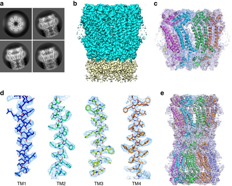
Figure 1
Density maps of INX-6 determined by cryo-EM.
( a ) Representative two-dimensional class averages of INX-6 in top and side views. ( b ) Three-dimensional structure of INX-6 hemichannel (cyan) in a side view. Densities in yellow represent a part o...
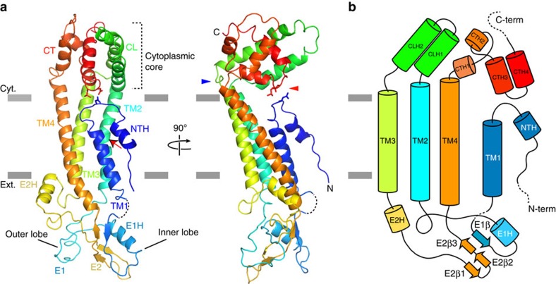
Figure 2
Monomeric structure of INX-6.
( a ) Ribbon representation of the INX-6 monomeric structure. TM2 is kinked at P122 (red arrow). The cytoplasmic core is connected to TM2, TM3 and TM4 with kinked loops (blue arrowhead). The N-termina...
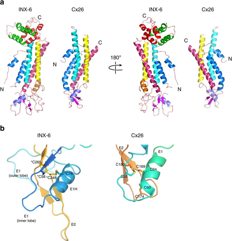
Figure 3
Similarity between the INX-6 and Cx26 monomers.
( a ) The monomeric structures of INX-6 and Cx26 (pdb code: 2zw3) 9 are presented side by side. Each transmembrane helix is coloured as follows: TM1 in blue, TM2 in cyan, TM3 in yellow and TM4 in pink...
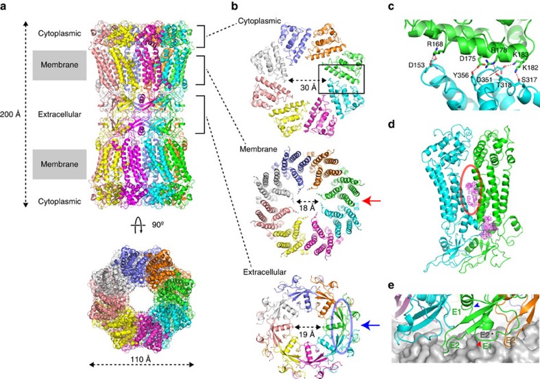
Figure 4
INX-6 gap junction structure and domain interface interactions.
( a ) Ribbon model of INX-6 gap junction channel in side view (top) and top view (bottom). ( b ) Three segments of INX-6. Cytoplasmic dome (cytoplasmic), transmembrane region (membrane) and extracellu...
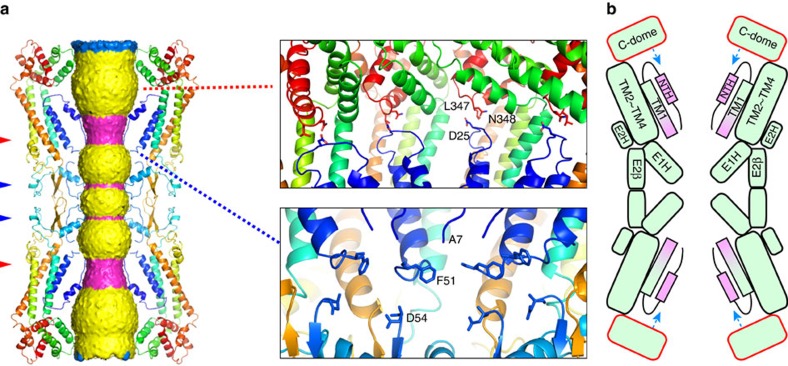
Figure 5
Pore pathway and regulation by the cytoplasmic dome of the INX-6 gap junction channel.
( a ) Surface representation of the pore pathway of the INX-6 gap junction channel. The surface is coloured as follows: magenta, diameter smaller than 19u2009u00c5; blue, diameter larger than 36u2009u...
Figure images are served from the NIH/NLM PubMed Central Open Access Subset or Europe PMC; copyright remains with the publishers and authors.
💬 Discussion
0 commentsNo comments yet. Be the first to start a discussion!
Leave a Comment