Abstract
Based on partially-coherent digital in-line holography, we report a field-portable microscope that can render lensfree colour images over a wide field-of-view of e.g., >20 mm(2). This computational holographic microscope weighs less than 145 grams with dimensions smaller than 17×6×5 cm, making it especially suitable for field settings and point-of-care use. In this lensfree imaging design, we merged a colorization algorithm with a source shifting based multi-height pixel super-resolution technique to mitigate 'rainbow' like colour artefacts that are typical in holographic imaging. This image processing scheme is based on transforming the colour components of an RGB image into YUV colour space, which separates colour information from brightness component of an image. The resolution of our super-resolution colour microscope was characterized using a USAF test chart to confirm sub-micron spatial resolution, even for reconstructions that employ multi-height phase recovery to handle dense and connected objects. To further demonstrate the performance of this colour microscope Papanicolaou (Pap) smears were also successfully imaged. This field-portable and wide-field computational colour microscope could be useful for tele-medicine applications in resource poor settings.
🔬 Techniques
💻 Software
✨ Fluorophores
🧪 Sample Preparation
🏭 Microscope Brands
💻 Software Details
🏛️ Research Organizations (ROR)
Affiliated research institutions:
📋 Methods
Field-portable colour microscope design
Our field-portable microscope (see Fig. 2 ) is designed to enable both pixel super-resolution and colour imaging by separating a set of low-cost LEDs that serve as the illumination source into two groups. The first group of LEDs enables pixel super-resolution imaging based on a shift of the source location; it contains 17 green LEDs that are butt-coupled to multi-mode fibers (each with 0.1 mm core diameter, Thorlabs, AFS-105/125Y). The emission of these green LEDs is also passed through a colour filter after each fiber end (bandwidth ∼ 3 nm, centred around 532 nm, Thorlabs, FL532-3) to achieve the temporal coherence that is required for capturing high NA in-line holograms at the detector plane. To implement pixel-super resolution by source shifting, these green LEDs of the first group are arranged into a line, which is tilted 45 degrees relative to the image sensor edges (see Fig. 2 .b), such that the acquired lensfree holograms can be sub-pixel shifted along both X and Y directions. The second group of LEDs enables the acquisition of lower resolution lensfree colour images, and it is composed of only three LEDs: one blue, one green, and one red, with λ = 470 nm, 527 nm and 625 nm, respectively. The illumination bandwidth of each one of these LEDs is rather broad, e.g., ∼ 45 nm, and since pixel super-resolution is not needed here, we did not employ a colour filter for these second group of LEDs. Each LED is still butt-coupled to a multi-mode fiber (0.1 mm core diameter), as illustrated in Fig. 2 .c. All these 20 LEDs are individually controlled by a micro-controller (Atmel, ATmega8515), which sequentially turns on and off each LED within the array, while the image sensor captures lensfree holograms. The image capture and illumination are controlled in LabVIEW, and consequently the entire imaging process, including auto-exposure, is fully automated and is controlled using a laptop computer with a USB connection to the field-portable microscope. The distance between the fibers’ free ends (which are cleaved) and the object plane is designed to be ∼ 6 cm for two reasons: first, to allow the partially-coherent illumination light to gain sufficient spatial coherence before impinging on the sample plane, and second to ensure that each LED will illuminate the sample with an angle that is less than three degrees compared to the surface normal. This restriction is of paramount importance for pixel-super resolution based microscopy, since it enables capturing the same cross-section of the object in each sub-pixel shifted transmission image. The above described multi-source illumination module is then connected to the sample holder and a cost-effective, custom-designed Z-stage (see Fig. 2 .b). This Z-stage has a coarse axial resolution of ∼ 10–15 µm, and it is used to move the CMOS sensor chip (1.67 µm pixel size, 10 mega-pixel, monochrome) up and down compared to the sample plane, which is required for achieving multi-height based phase-recovery. This multi-height phase-recovery process enables imaging of dense and connected samples, such as pathology slides, by iteratively eliminating the twin image noise, which is an artefact of in-line holography. This Z-stage is custom built from a lens-tube (Thorlabs, SM1L03) and a threading adapter (Thorlabs, SM1A10), which is glued to the field-portable microscope enclosure. Digital colorization of lensfree holographic images To obtain high fidelity colour reproduction of the imaged object, three sequential lensfree holograms are initially acquired, each with a different illumination wavelength: blue, green and red (λ = 470 nm, 527 nm and 625 nm, respectively). Then, the background mean values of these holograms are equalized to digitally compensate for power and fiber coupling efficiency variations between different LEDs in our microscope design. These resulting in-line holograms are then back propagated to the object plane (see Fig. 3 .a). If these in-line holograms were simply combined into an RGB image [43] , a ‘rainbow’ like colour artefact would corrupt the image [43] – [47] . Therefore, to mitigate this artefact, the lensfree RGB image is initially converted into the YUV colour space using Colorspace Transformations package that is processed in MATLAB. The YUV colour space separates the brightness information (Y channel) from the colour information of the image (U and V channels), and therefore by averaging only the colour components with a rectangular window (∼ 13 µm edge size), the ‘rainbow’ like colour artefact of lensfree holographic images can be mitigated ( Fig. 3 .a). However, the spatial resolution of the resulting image becomes relatively low, and to enhance its resolution, the brightness component (Y channel) is entirely replaced by the pixel super-resolved image of the object ( Fig. 3 .b), which is obtained by using 17 green LEDs that are butt-coupled to a linear array of multi-mode fiber optic cables, as detailed earlier. The resulting colour image has the brightness component (Y channel) from Fig. 3 .b that is super-resolved, and the colour information (U-V channels) from Fig. 3 .a. To further enhance the contrast of important sub-cellular features such as cell nuclei, which are typically absorbing and characterized by low intensity values in their lensfree transmission images, dark areas within the brightness (Y) channel were not coloured. These dark areas of an image were detected by thresholding the super-resolved brightness image. The resulting ‘hybrid’ YUV image is then converted back to RGB colour space to achieve high fidelity colour representation, as illustrated in Fig. 3 .c, which is in very good agreement with a conventional lens-based microscope image of the same sample. Source shifting based pixel super-resolution Pixel super-resolution is a computational method that synthesizes one high-resolution image from a set of sub-pixel shifted lower resolution images of the same scene/object [53] – [58] . The resulting high-resolution image is effectively equivalent to digitizing the object with a smaller pixel-size sensor. In our field-portable microscope, we shift the light source (LED) location by sequentially illuminating the sample with 17 colour filtered LEDs ( Fig. 2 .b), each of which is butt-coupled to a multi-mode fiber. The sub-pixel shifts between different holograms are evaluated automatically by implementing an iterative gradient method [55] . These relative shifts together with the lower resolution raw holograms are then provided as inputs to a least-square optimization problem to estimate a high-resolution (i.e., super-resolved) hologram that is consistent with the lower resolution measured lensfree holograms, while also penalizing for high-frequency components that might arise due to measurement noise. This optimization problem can be quickly solved by a conjugate gradient method [53] , which typically converges within ∼10 iterations. Multi-height phase-recovery A well-known artefact of in-line holography is the twin image noise, which corrupts the reconstructed holograms especially for spatially dense and connected samples [59] . To mitigate this twin image noise, various phase-recovery approaches were devised [36] , [59] . In this work, we implemented a multi-height phase-recovery approach since it does not need prior knowledge about the object shape or dimensions [60] – [64] . This iterative phase recovery approach uses few intensity measurements (e.g., 3–4), where each measurement is obtained at a different sample to sensor distance (i.e., height). The multi-height phase-recovery approach propagates the super-resolved holograms between different heights, and at each step the algorithm enforces the super-resolved hologram intensity, while keeping the resulting phase from the previous iteration untouched. After several iterations (e.g., 5–10) the missing phase is retrieved and the twin image noise is significantly suppressed. In our implementation, to change the distance between the image sensor and the sample planes, a cost-effective and custom-designed Z-stage was used (see Fig. 2 ). In case the sample is too thick to fit into the insertion tray of our microscope, various glass cover slips with different thicknesses can also be placed between the sample and the image sensor to change the sample’s height compared to the sensor chip. An auto-focus algorithm was also implemented to automatically estimate the sample to sensor distance for each raw hologram without the need for an independent measurement of the sample height [14] . Hologram reconstruction - focusing back to the object plane After the phase recovery steps described earlier, the final holographic reconstruction process includes the multiplication of the complex hologram with a reference wave, which in our imaging geometry can be approximated as a plane wave. The hologram can then be back propagated to the object plane by using the free space transfer function in the frequency domain [59] . This computational step results in a complex image, containing both the amplitude and phase information of the objects.
Show full methods section
Field-portable colour microscope design
Our field-portable microscope (see Fig. 2 ) is designed to enable both pixel super-resolution and colour imaging by separating a set of low-cost LEDs that serve as the illumination source into two groups. The first group of LEDs enables pixel super-resolution imaging based on a shift of the source location; it contains 17 green LEDs that are butt-coupled to multi-mode fibers (each with 0.1 mm core diameter, Thorlabs, AFS-105/125Y). The emission of these green LEDs is also passed through a colour filter after each fiber end (bandwidth ∼ 3 nm, centred around 532 nm, Thorlabs, FL532-3) to achieve the temporal coherence that is required for capturing high NA in-line holograms at the detector plane. To implement pixel-super resolution by source shifting, these green LEDs of the first group are arranged into a line, which is tilted 45 degrees relative to the image sensor edges (see Fig. 2 .b), such that the acquired lensfree holograms can be sub-pixel shifted along both X and Y directions. The second group of LEDs enables the acquisition of lower resolution lensfree colour images, and it is composed of only three LEDs: one blue, one green, and one red, with λ = 470 nm, 527 nm and 625 nm, respectively. The illumination bandwidth of each one of these LEDs is rather broad, e.g., ∼ 45 nm, and since pixel super-resolution is not needed here, we did not employ a colour filter for these second group of LEDs. Each LED is still butt-coupled to a multi-mode fiber (0.1 mm core diameter), as illustrated in Fig. 2 .c. All these 20 LEDs are individually controlled by a micro-controller (Atmel, ATmega8515), which sequentially turns on and off each LED within the array, while the image sensor captures lensfree holograms. The image capture and illumination are controlled in LabVIEW, and consequently the entire imaging process, including auto-exposure, is fully automated and is controlled using a laptop computer with a USB connection to the field-portable microscope. The distance between the fibers’ free ends (which are cleaved) and the object plane is designed to be ∼ 6 cm for two reasons: first, to allow the partially-coherent illumination light to gain sufficient spatial coherence before impinging on the sample plane, and second to ensure that each LED will illuminate the sample with an angle that is less than three degrees compared to the surface normal. This restriction is of paramount importance for pixel-super resolution based microscopy, since it enables capturing the same cross-section of the object in each sub-pixel shifted transmission image. The above described multi-source illumination module is then connected to the sample holder and a cost-effective, custom-designed Z-stage (see Fig. 2 .b). This Z-stage has a coarse axial resolution of ∼ 10–15 µm, and it is used to move the CMOS sensor chip (1.67 µm pixel size, 10 mega-pixel, monochrome) up and down compared to the sample plane, which is required for achieving multi-height based phase-recovery. This multi-height phase-recovery process enables imaging of dense and connected samples, such as pathology slides, by iteratively eliminating the twin image noise, which is an artefact of in-line holography. This Z-stage is custom built from a lens-tube (Thorlabs, SM1L03) and a threading adapter (Thorlabs, SM1A10), which is glued to the field-portable microscope enclosure. Digital colorization of lensfree holographic images To obtain high fidelity colour reproduction of the imaged object, three sequential lensfree holograms are initially acquired, each with a different illumination wavelength: blue, green and red (λ = 470 nm, 527 nm and 625 nm, respectively). Then, the background mean values of these holograms are equalized to digitally compensate for power and fiber coupling efficiency variations between different LEDs in our microscope design. These resulting in-line holograms are then back propagated to the object plane (see Fig. 3 .a). If these in-line holograms were simply combined into an RGB image [43] , a ‘rainbow’ like colour artefact would corrupt the image [43] – [47] . Therefore, to mitigate this artefact, the lensfree RGB image is initially converted into the YUV colour space using Colorspace Transformations package that is processed in MATLAB. The YUV colour space separates the brightness information (Y channel) from the colour information of the image (U and V channels), and therefore by averaging only the colour components with a rectangular window (∼ 13 µm edge size), the ‘rainbow’ like colour artefact of lensfree holographic images can be mitigated ( Fig. 3 .a). However, the spatial resolution of the resulting image becomes relatively low, and to enhance its resolution, the brightness component (Y channel) is entirely replaced by the pixel super-resolved image of the object ( Fig. 3 .b), which is obtained by using 17 green LEDs that are butt-coupled to a linear array of multi-mode fiber optic cables, as detailed earlier. The resulting colour image has the brightness component (Y channel) from Fig. 3 .b that is super-resolved, and the colour information (U-V channels) from Fig. 3 .a. To further enhance the contrast of important sub-cellular features such as cell nuclei, which are typically absorbing and characterized by low intensity values in their lensfree transmission images, dark areas within the brightness (Y) channel were not coloured. These dark areas of an image were detected by thresholding the super-resolved brightness image. The resulting ‘hybrid’ YUV image is then converted back to RGB colour space to achieve high fidelity colour representation, as illustrated in Fig. 3 .c, which is in very good agreement with a conventional lens-based microscope image of the same sample. Source shifting based pixel super-resolution Pixel super-resolution is a computational method that synthesizes one high-resolution image from a set of sub-pixel shifted lower resolution images of the same scene/object [53] – [58] . The resulting high-resolution image is effectively equivalent to digitizing the object with a smaller pixel-size sensor. In our field-portable microscope, we shift the light source (LED) location by sequentially illuminating the sample with 17 colour filtered LEDs ( Fig. 2 .b), each of which is butt-coupled to a multi-mode fiber. The sub-pixel shifts between different holograms are evaluated automatically by implementing an iterative gradient method [55] . These relative shifts together with the lower resolution raw holograms are then provided as inputs to a least-square optimization problem to estimate a high-resolution (i.e., super-resolved) hologram that is consistent with the lower resolution measured lensfree holograms, while also penalizing for high-frequency components that might arise due to measurement noise. This optimization problem can be quickly solved by a conjugate gradient method [53] , which typically converges within ∼10 iterations. Multi-height phase-recovery A well-known artefact of in-line holography is the twin image noise, which corrupts the reconstructed holograms especially for spatially dense and connected samples [59] . To mitigate this twin image noise, various phase-recovery approaches were devised [36] , [59] . In this work, we implemented a multi-height phase-recovery approach since it does not need prior knowledge about the object shape or dimensions [60] – [64] . This iterative phase recovery approach uses few intensity measurements (e.g., 3–4), where each measurement is obtained at a different sample to sensor distance (i.e., height). The multi-height phase-recovery approach propagates the super-resolved holograms between different heights, and at each step the algorithm enforces the super-resolved hologram intensity, while keeping the resulting phase from the previous iteration untouched. After several iterations (e.g., 5–10) the missing phase is retrieved and the twin image noise is significantly suppressed. In our implementation, to change the distance between the image sensor and the sample planes, a cost-effective and custom-designed Z-stage was used (see Fig. 2 ). In case the sample is too thick to fit into the insertion tray of our microscope, various glass cover slips with different thicknesses can also be placed between the sample and the image sensor to change the sample’s height compared to the sensor chip. An auto-focus algorithm was also implemented to automatically estimate the sample to sensor distance for each raw hologram without the need for an independent measurement of the sample height [14] . Hologram reconstruction - focusing back to the object plane After the phase recovery steps described earlier, the final holographic reconstruction process includes the multiplication of the complex hologram with a reference wave, which in our imaging geometry can be approximated as a plane wave. The hologram can then be back propagated to the object plane by using the free space transfer function in the frequency domain [59] . This computational step results in a complex image, containing both the amplitude and phase information of the objects.
📊 Figures
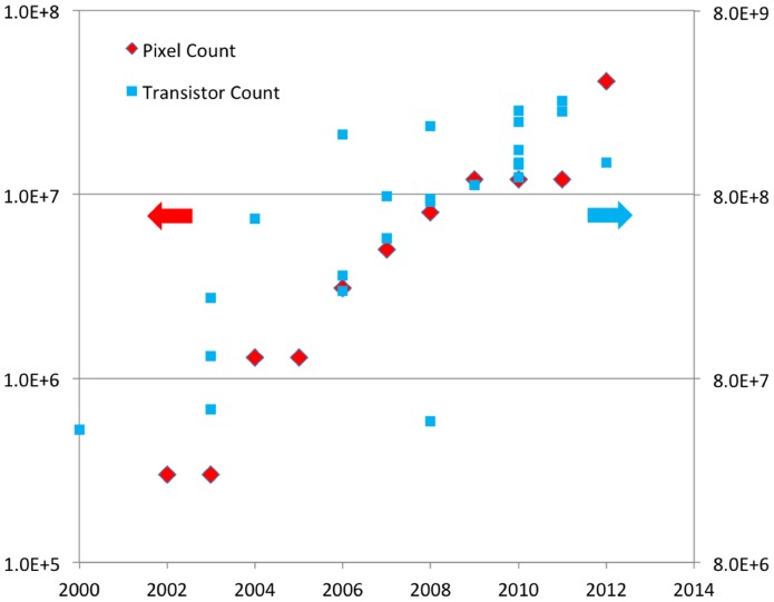
Figure 1
A different view of Mooreu2019s law.
A comparison of transistor counts in central processing units (CPUs) versus the pixel counts on cellular phone cameras. The transistor count has several data points for each year, while the cellular p...
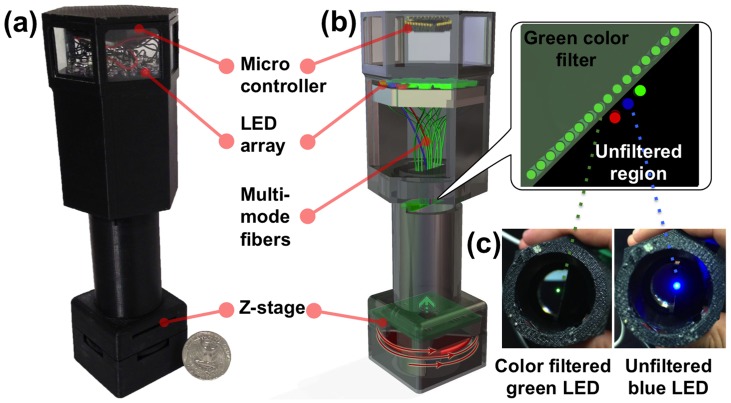
Figure 2
A portable lensfree super-resolution colour microscope.
(a) A photograph of the microscope that weighs < 145 grams. (b) A schematic diagram of the microscope; the LED array is separated into two groups, the first group enables pixel super-resolution bas...
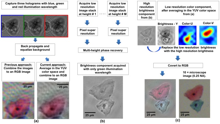
Figure 3
Image processing block diagrams.
(a) For creating a lower resolution colour image of the specimen, three lower resolution holograms are acquired, each with a different illumination wavelength (u03bb u200a=u200a 470 nm, 527 nm and 625...
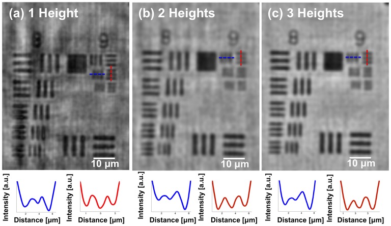
Figure 4
Quantification of the spatial resolution as a function of the number of heights used in our multi-height phase-recovery process.
(a) Amplitude image that was reconstructed using one height. (b) Amplitude image that was reconstructed using two heights. (c) Amplitude image that was reconstructed using three heights. Cross section...
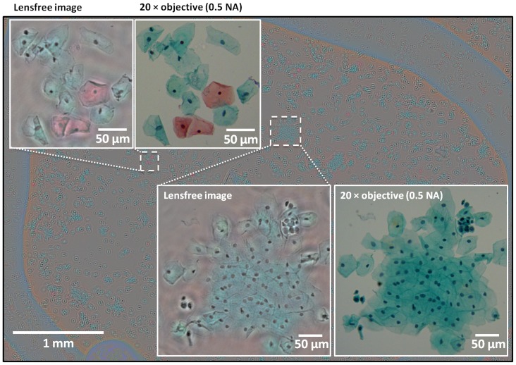
Figure 5
A wide FOV (u223c21 mm 2 ) lensfree colour image of a Pap smear sample (ThinPrepu00ae preparation).
The Pap test was reconstructed using pixel super-resolved holograms acquired at four different heights (1069 u00b5m, 1117 u00b5m, 1159 u00b5m and 1205 u00b5m). For comparison purposes, 20u00d7 microsc...
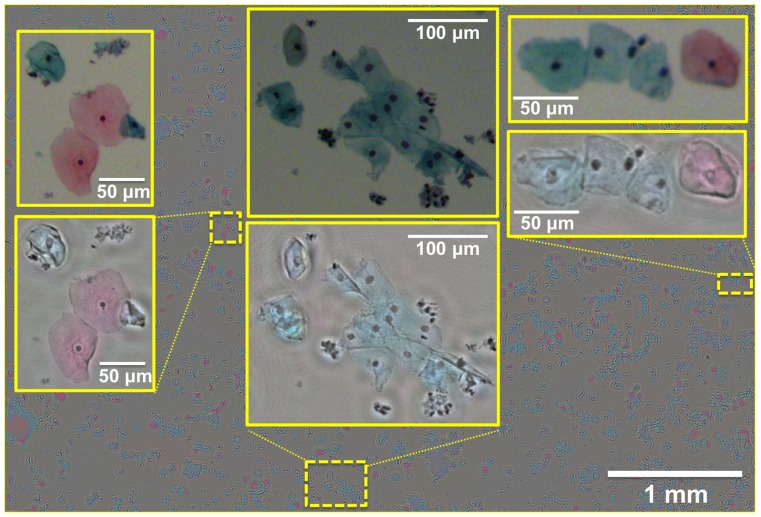
Figure 6
A wide FOV (u223c21 mm 2 ) lensfree colour image of a Pap smear sample (ThinPrepu00ae preparation).
The Pap test was reconstructed using pixel super-resolved holograms acquired at three different heights (860 u00b5m, 1040 u00b5m and 1080 u00b5m). For comparison purposes, 10u00d7 microscopes images (...
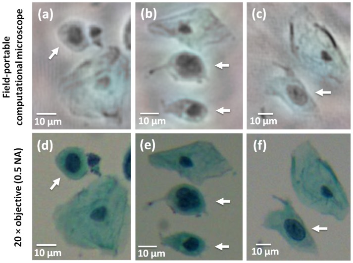
Figure 7
Lensfree computational images of abnormal cells in a Pap smear sample.
(a), (b) and (c) lensfree Pap smear images of abnormal cells (pointed by white arrows), which generally exhibit large nucleus in comparison to their cytoplasm as well as an irregular cytoplasm shape. ...
Figure images are served from the NIH/NLM PubMed Central Open Access Subset or Europe PMC; copyright remains with the publishers and authors.
💬 Discussion
0 commentsNo comments yet. Be the first to start a discussion!
Leave a Comment