Abstract
Line-field confocal optical coherence tomography (LC-OCT) is a non-invasive optical imaging technique based on a combination of the principles of optical coherence tomography and reflectance confocal microscopy with line-field illumination, which can generate cell-resolved images of the skin in vivo. This article reports on the LC-OCT technique and its application in dermatology. The principle of the technique is described, and the latest technological innovations are presented. The technology has been miniaturized to fit within an ergonomic handheld probe, allowing for the easy access of any skin area on the body. The performance of the LC-OCT device in terms of resolution, field of view, and acquisition speed is reported. The use of LC-OCT in dermatology for the non-invasive detection, characterization, and therapeutic follow-up of various skin pathologies is discussed. Benign and malignant melanocytic lesions, non-melanocytic skin tumors, such as basal cell carcinoma, squamous cell carcinoma and actinic keratosis, and inflammatory and infectious skin conditions are considered. Dedicated deep learning algorithms have been developed for assisting in the analysis of LC-OCT images of skin lesions.
🔬 Techniques
🔬 Cell Lines
🏭 Microscope Brands
🔴 Lasers
🏛️ Research Organizations (ROR)
Affiliated research institutions:
📋 Methods
2.1. The LC-OCT Imaging Device 2.1.1. deepLive™ The LC-OCT technique is based on a combination of OCT and RCM with the illumination of the skin with a focused line of light [ 23 ]. A vertical section image (a B-scan) is obtained from several depth-profiles (A-scans) acquired in parallel by a line-scan camera. Vertical sections can be obtained in real time by scanning in depth at a frequency of a few Hertz, enabling the focus of a microscope objective to be dynamically adjusted. Cross-sectional images in a horizontal plane (en face sections) at an adjustable depth can also be obtained by laterally scanning the illumination line focused on this plane [ 24 ]. Finally, 3-dimensional images can be obtained from a stack of horizontal (en face) sections [ 24 ]. In addition, images of the skin surface can be acquired simultaneously with the LC-OCT images using an auxiliary imaging system incorporated in the LC-OCT device. The LC-OCT technology has been industrially developed by DAMAE Medical. Since the company was founded in 2014, several generations of LC-OCT devices have been designed and developed following technical improvement plans. A first clinical demonstrator, composed of a microscope-shaped LC-OCT device, was developed in 2016 and released for investigative use only [ 23 ]. Following design and engineering studies, a miniaturized probe device was developed in 2018 incorporating LC-OCT technology. This device was CE-marked in class I for clinical research purposes, and 2 units were manufactured and installed in key-opinion leader (KOL) dermatology practices. Scientific research and technological experiments allowed for the extension of LC-OCT technology to 3D imaging [ 24 ]. A new device was then developed to integrate this latest innovation, leading to the release in 2019 of a pilot series of 10 device units installed in KOL practices. This new version was also CE-marked in class I for clinical research purposes. Finally, following a new iteration of technical improvements and design robustification, the first commercial version of the product, named deepLive™ (see Figure 1 ), was CE-marked in class I and released in 2020. The industrialization of the device supported the development of commercial activities of the company in the European dermatology market. In 2023, due to the evolution of the European Union medical device regulation and based on clinical evidence generated by clinical studies conducted with KOL partners, deepLive™ was CE-marked in class IIa with the intended use of assisting dermatologists with skin cancer diagnostics. To date (November 2023), DAMAE Medical has installed over 50 devices worldwide, mainly in Europe (France, Germany, and Italy), as well as in the USA. A button and a scroll wheel on the deepLive™ probe handle allows the user to select the imaging mode (vertical, horizontal, or 3D) and to adjust the lateral/depth positions in the vertical/horizontal real-time imaging modes. Clicking on the button starts image recording. DAMAE Medical has developed user-friendly software connected to the imaging device. A patient file can be created by registering their demographic information and indicating the lesion location on a designed body mapper. The recorded LC-OCT images with their associated dermoscopy images can be reviewed. Image stacks can be displayed as texture-based volume renderings or orthoslices. For specific needs, various custom image processing algorithms are available to facilitate image review and analysis. Additionally, deepLive™ software V1.6.1 allows for the registration of clinical suspicions, LC-OCT diagnosis, patient management, and histological diagnosis to facilitate patient follow-up. The complete typical patient examination procedure with deepLive™ is described in detail in [ 25 ]. 2.1.2. Technical Description The experimental setup of LC-OCT is shown schematically in Figure 2 . It is based on a two-beam interferometer with a microscope objective in each of the two interferometer arms (sample arm and reference arm). A supercontinuum fiber laser (SuperK EVO, NKT photonics, Birkerød, Denmark) is used as a broadband spatially coherent light source at a detected central wavelength of ~800 nm. Light emitted by a single mode photonic crystal fiber passes through a collimator and a cylindrical lens to generate a line of light focused on the skin and on a plane reference surface by the microscope objectives (UMPLFLN 20XW, water immersion, 20X, numerical aperture of 0.5, Olympus, Tokyo, Japan). The image of this line is projected on the sensor of a line-scan camera (Octoplus, 2048 pixels, Teledyne e2v, Chelmsford, UK). Silicone oil is used as an immersion medium with a refractive index of 1.4, close to the mean refractive index of skin. A 500 μ m thick glass window is placed under each microscope objective to stabilize the skin in the sample arm and provide a low-reflectivity (3.5%) plane reference reflector in the reference arm. When imaging the skin, a film of paraffin oil is deposited between the skin and the glass window to provide refractive index matching between the window and the skin, diminishing the specular back-reflection from both the skin surface and the glass window. The whole interferometer is mounted on a piezoelectric (PZT) linear translation stage (P625.1CD, Physik Instrument, Karlsruhe, Germany) for scanning into the depth ( z ) of the skin. The interferometer sample arm includes a mirror galvanometer (6210H, Cambridge Technology, Bedford, MA, USA) for lateral ( y ) scanning of the line of light for en face imaging (horizontal imaging mode). The reference reflector is attached to a piezoelectric (PZT) chip, which can oscillate to generate a phase modulation for en face imaging. An auxiliary imaging system is incorporated in the LC-OCT device for imaging the skin surface like a dermoscope (see Figure 2 ). A ring of light-emitting diodes (LEDs) surrounds the microscope objective in the sample arm to illuminate the skin with white light. A beamsplitter mounted on the galvanometer scanner separates the light used for LC-OCT and the light used for dermoscopy. The light transmitted by the dichroic filter is collected by an afocal optical system and sent towards a color-area camera equipped with a micro-objective. The focus of the micro-objective is adjusted dynamically and automatically, so that the image of the skin surface is always in focus, even when the microscope objective is scanned in depth for the LC-OCT image acquisitions. The LC-OCT images and the dermoscopy images are acquired simultaneously and are intrinsically co-localized as they are acquired using the same microscope objective. The field of view of the surface image is 2.6 mm diameter disk. The resolution of the surface image is 5 µm, which enables the observation of the same features as in conventional dermoscopy and therefore provides a direct link between the LC-OCT examination and the dermoscopic examination. The LC-OCT images can thus be acquired in regions of interest identified with the integrated dermoscopy modality. 2.2. The LC-OCT Imaging Modes 2.2.1.
Show full methods section
2.1. The LC-OCT Imaging Device 2.1.1. deepLive™ The LC-OCT technique is based on a combination of OCT and RCM with the illumination of the skin with a focused line of light [ 23 ]. A vertical section image (a B-scan) is obtained from several depth-profiles (A-scans) acquired in parallel by a line-scan camera. Vertical sections can be obtained in real time by scanning in depth at a frequency of a few Hertz, enabling the focus of a microscope objective to be dynamically adjusted. Cross-sectional images in a horizontal plane (en face sections) at an adjustable depth can also be obtained by laterally scanning the illumination line focused on this plane [ 24 ]. Finally, 3-dimensional images can be obtained from a stack of horizontal (en face) sections [ 24 ]. In addition, images of the skin surface can be acquired simultaneously with the LC-OCT images using an auxiliary imaging system incorporated in the LC-OCT device. The LC-OCT technology has been industrially developed by DAMAE Medical. Since the company was founded in 2014, several generations of LC-OCT devices have been designed and developed following technical improvement plans. A first clinical demonstrator, composed of a microscope-shaped LC-OCT device, was developed in 2016 and released for investigative use only [ 23 ]. Following design and engineering studies, a miniaturized probe device was developed in 2018 incorporating LC-OCT technology. This device was CE-marked in class I for clinical research purposes, and 2 units were manufactured and installed in key-opinion leader (KOL) dermatology practices. Scientific research and technological experiments allowed for the extension of LC-OCT technology to 3D imaging [ 24 ]. A new device was then developed to integrate this latest innovation, leading to the release in 2019 of a pilot series of 10 device units installed in KOL practices. This new version was also CE-marked in class I for clinical research purposes. Finally, following a new iteration of technical improvements and design robustification, the first commercial version of the product, named deepLive™ (see Figure 1 ), was CE-marked in class I and released in 2020. The industrialization of the device supported the development of commercial activities of the company in the European dermatology market. In 2023, due to the evolution of the European Union medical device regulation and based on clinical evidence generated by clinical studies conducted with KOL partners, deepLive™ was CE-marked in class IIa with the intended use of assisting dermatologists with skin cancer diagnostics. To date (November 2023), DAMAE Medical has installed over 50 devices worldwide, mainly in Europe (France, Germany, and Italy), as well as in the USA. A button and a scroll wheel on the deepLive™ probe handle allows the user to select the imaging mode (vertical, horizontal, or 3D) and to adjust the lateral/depth positions in the vertical/horizontal real-time imaging modes. Clicking on the button starts image recording. DAMAE Medical has developed user-friendly software connected to the imaging device. A patient file can be created by registering their demographic information and indicating the lesion location on a designed body mapper. The recorded LC-OCT images with their associated dermoscopy images can be reviewed. Image stacks can be displayed as texture-based volume renderings or orthoslices. For specific needs, various custom image processing algorithms are available to facilitate image review and analysis. Additionally, deepLive™ software V1.6.1 allows for the registration of clinical suspicions, LC-OCT diagnosis, patient management, and histological diagnosis to facilitate patient follow-up. The complete typical patient examination procedure with deepLive™ is described in detail in [ 25 ]. 2.1.2. Technical Description The experimental setup of LC-OCT is shown schematically in Figure 2 . It is based on a two-beam interferometer with a microscope objective in each of the two interferometer arms (sample arm and reference arm). A supercontinuum fiber laser (SuperK EVO, NKT photonics, Birkerød, Denmark) is used as a broadband spatially coherent light source at a detected central wavelength of ~800 nm. Light emitted by a single mode photonic crystal fiber passes through a collimator and a cylindrical lens to generate a line of light focused on the skin and on a plane reference surface by the microscope objectives (UMPLFLN 20XW, water immersion, 20X, numerical aperture of 0.5, Olympus, Tokyo, Japan). The image of this line is projected on the sensor of a line-scan camera (Octoplus, 2048 pixels, Teledyne e2v, Chelmsford, UK). Silicone oil is used as an immersion medium with a refractive index of 1.4, close to the mean refractive index of skin. A 500 μ m thick glass window is placed under each microscope objective to stabilize the skin in the sample arm and provide a low-reflectivity (3.5%) plane reference reflector in the reference arm. When imaging the skin, a film of paraffin oil is deposited between the skin and the glass window to provide refractive index matching between the window and the skin, diminishing the specular back-reflection from both the skin surface and the glass window. The whole interferometer is mounted on a piezoelectric (PZT) linear translation stage (P625.1CD, Physik Instrument, Karlsruhe, Germany) for scanning into the depth ( z ) of the skin. The interferometer sample arm includes a mirror galvanometer (6210H, Cambridge Technology, Bedford, MA, USA) for lateral ( y ) scanning of the line of light for en face imaging (horizontal imaging mode). The reference reflector is attached to a piezoelectric (PZT) chip, which can oscillate to generate a phase modulation for en face imaging. An auxiliary imaging system is incorporated in the LC-OCT device for imaging the skin surface like a dermoscope (see Figure 2 ). A ring of light-emitting diodes (LEDs) surrounds the microscope objective in the sample arm to illuminate the skin with white light. A beamsplitter mounted on the galvanometer scanner separates the light used for LC-OCT and the light used for dermoscopy. The light transmitted by the dichroic filter is collected by an afocal optical system and sent towards a color-area camera equipped with a micro-objective. The focus of the micro-objective is adjusted dynamically and automatically, so that the image of the skin surface is always in focus, even when the microscope objective is scanned in depth for the LC-OCT image acquisitions. The LC-OCT images and the dermoscopy images are acquired simultaneously and are intrinsically co-localized as they are acquired using the same microscope objective. The field of view of the surface image is 2.6 mm diameter disk. The resolution of the surface image is 5 µm, which enables the observation of the same features as in conventional dermoscopy and therefore provides a direct link between the LC-OCT examination and the dermoscopic examination. The LC-OCT images can thus be acquired in regions of interest identified with the integrated dermoscopy modality. 2.2. The LC-OCT Imaging Modes 2.2.1.
Vertical Imaging
A vertical section LC-OCT image is acquired by activating the PZT stage to scan into the depth of skin tissues. The PZT stage oscillates at a frequency of 8 Hz according to asymetrical sawthooths with a duty cycle of 80%. The effective amplitude of the scanned depth is Z = 400 μ m . The camera frame rate is set to 70 kHz so that the step between two consecutive lines acquired by the camera during the displacement of the PZT stage is δ = 70 nm , corresponding to a phase-shift of π / 2 . A stack of Z / δ = 5700 lines is acquired during each positive slope of the depth scan. A vertical section image is generated by applying a five-frame fringe envelope detection algorithm [ 26 ] to the acquired stack of lines. Acquisition and data processing is repeated continuously during the oscillation cycles of the PZT stage. The resulting images are displayed at a rate of 8 frames/s with automatic contrast optimization following appropriate rescaling. The size of each vertical section image is 2048 × 680 pixels ( x × z ), corresponding to a field of view of 1.2 mm × 0.4 mm ( x × z ). The axial resolution ( z direction) and the lateral resolution ( x direction) are identical, equal to 1.3 µm. The angle of the mirror galvanometer can be controlled by the scroll wheel on the probe handle to change the lateral ( y ) position of the vertical section. This allows for navigation laterally through the sample being imaged, in real time, with a positioning accuracy far superior to that obtained by moving the probe manually. An example of a vertical cross-sectional LC-OCT image of healthy skin (forearm of a 25-year-old woman) is shown in Figure 3 . The vertical section view enables the visualization of the upper layers and structures of the skin at a cellular resolution, similar to conventional histology. The stratum corneum (SC), viable epidermis (VE), and dermis (D) can be differentiated with the clear dermal-epidermal junction (DEJ). Keratinocyte nuclei are revealed in the viable epidermis. On the surface image, a red line indicates where the LC-OCT vertical section is being acquired. 2.2.2.
Horizontal Imaging
In the horizontal imaging mode, the mirror galvanometer operates by executing asymmetrical sawtooth oscillations at a frequency of 8 Hz. These oscillations serve to laterally scan the illumination line (in the y-axis direction) across a 500 µm field. The camera frame rate is set to 100 kHz . Two consecutive lines acquired by the camera are thus separated by a lateral distance of 50 nm. A stack of 10 , 000 lines is acquired during each positive slope of the lateral scan. The reference reflector of the interferometer is attached to a PZT chip, which oscillates sinusoidally to generate a phase modulation. The frequency and amplitude of the PZT chip oscillation are empirically set at 8 kHz and 1 µm, respectively. A phase-shifting algorithm with sinusoidal phase modulation is used to extract the envelope of the interference fringes [ 27 ]. This algorithm processes an algebraic combination of four consecutive lines acquired by the camera to obtain each line of the horizontal section image. The acquisition and data processing procedures are continuously repeated as the mirror galvanometer oscillates back and forth. The horizontal section images are displayed in real time at 8 frames/s with automatically optimized contrast after being appropriately rescaled. The size of each horizontal section image is 2048 × 850 pixels ( x × y ), corresponding to a field of view of 1.2 mm × 0.5 mm ( x × y ). The lateral resolutions in the x and y directions are similar, around 1.3 µm. For user convenience, the imaging depth can be adjusted from 0 to 500 µm using the scroll wheel on the probe handle. A horizontal section LC-OCT image of healthy skin (forearm of a 25-year-old woman) is shown in Figure 4 . This image, acquired at a depth of 35 µm, corresponds to a section through the epidermis (stratum spinosum). The keratinocyte nuclei and the honeycomb architecture of the keratinocytes can be clearly visualized. On the surface image, a blue rectangle indicates where the horizontal LC-OCT image is acquired. 2.2.3. Three-Dimensional Imaging Three-dimensional (3D) images can be generated in less that 25 s from a stack of horizontal sections acquired at successive depths with a step of 1 µm. The resulting 3D image of 2048 × 850 × 500 pixels ( x × y × z ) is rescaled to 1200 × 500 × 500 pixels for a proper aspect ratio, corresponding to a volume of 1.2 × 0.5 × 0.5 mm 3 ( x × y × z ). In practical usage, the 3D imaging mode is selected by the user through the probe handle. By clicking the scroll wheel and turning it in the appropriate direction, the user can choose between 3D image acquisition and video recording. Once 3D acquisition has started, both the PZT stage and the mirror galvanometer move continuously until the PZT stage reaches a depth of 500 µm. When 3D acquisition is complete, the system reverts to the vertical or horizontal imaging mode prior to 3D acquisition. Figure 5 shows a 3D LC-OCT image of healthy skin (forearm of a 25-year-old woman). The volume-rendering visualization makes it possible to observe the three-dimensional architecture and connections of the structures in the skin at cellular level, which is not accessible by conventional histology. On the surface image, a blue rectangle indicates where the 3D image is acquired, allowing for easy positioning by the user.
📊 Figures
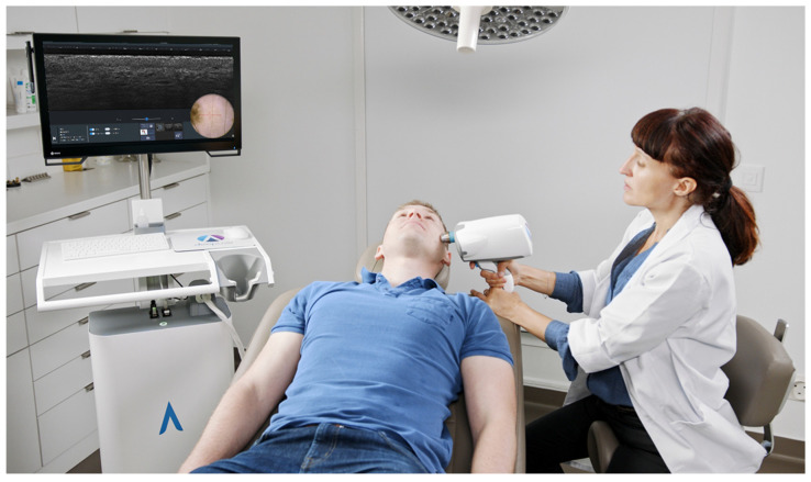
Figure 1
Line-field confocal optical coherence tomography (LC-OCT) device (deepLiveu2122) commercialized by DAMAE Medical.
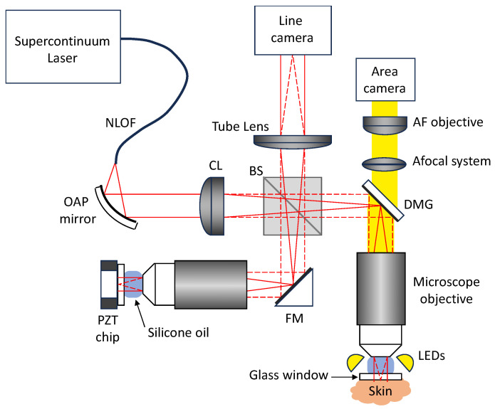
Figure 2
Schematic diagram of the LC-OCT device. NLOF: non-linear optical fiber; OAP: off-axis parabolic mirror; CL: cylindrical lens; BS: beamsplitter; FM: fold mirror; DMG: dichroic mirror galvanometer; LEDs...
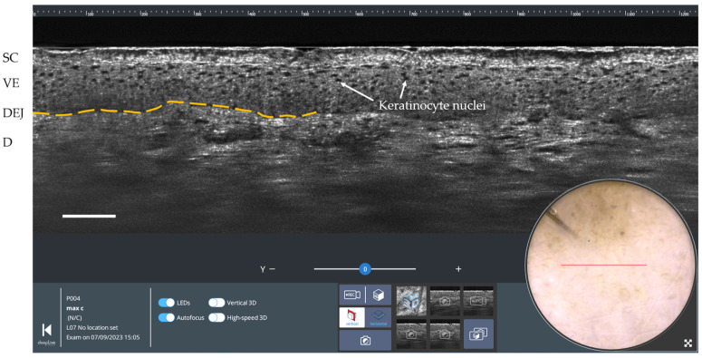
Figure 3
Vertical LC-OCT and dermoscopy image of healthy skin using deepLiveu2122 software. Scale bar: 100 u00b5m. The red horizontal line superimposed on the dermoscopic image delineates the location of the v...

Figure 4
Horizontal LC-OCT and dermoscopy image of healthy skin using deepLiveu2122 software. Scale bar: 100 u00b5m. The blue rectangle superimposed on the dermoscopic image delineates the location of the hori...
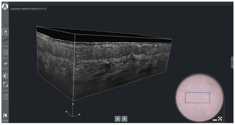
Figure 5
3D LC-OCT rendering and dermoscopy of healthy skin using deepLiveu2122 software. The blue rectangle superimposed on the dermoscopic image delineates the location of the stack of horizontal sectional L...
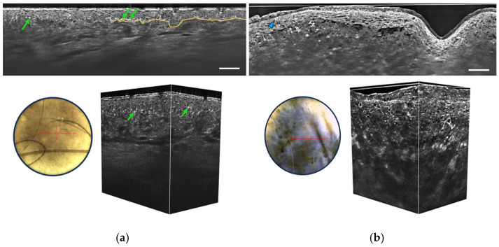
Figure 6
Vertical sectional LC-OCT image, dermoscopic image (left), and 3D LC-OCT reconstruction (right) of a junctional nevus ( a ) and a melanoma ( b ). The red horizontal line superimposed on the dermoscopi...
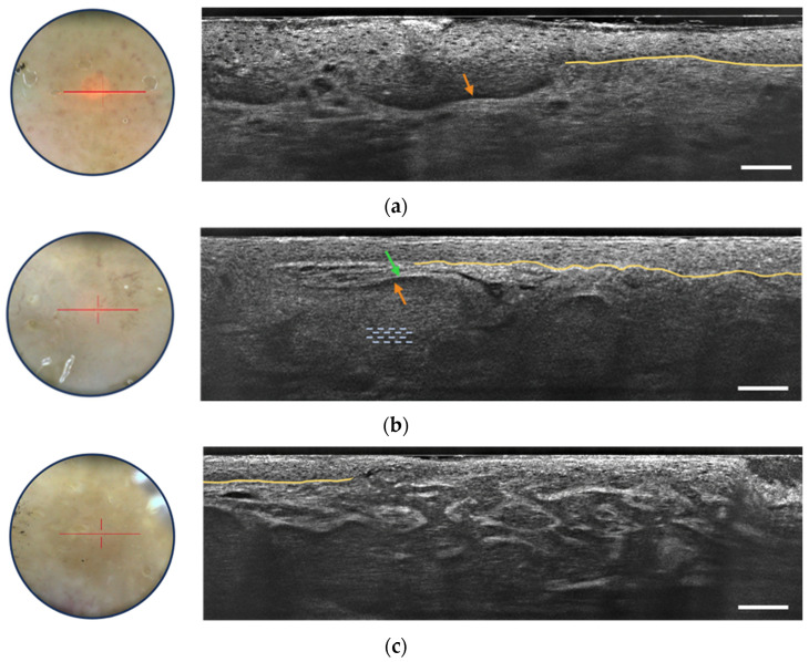
Figure 7
Dermoscopic image (left) and vertical sectional LC-OCT image (right) of a superficial basal cell carcinoma (BCC) ( a ), a nodular BCC ( b ) and an infiltrative BCC ( c ). The core of the lobule is cha...

Figure 8
Dermoscopic image ( left ) and vertical sectional LC-OCT image ( right ) of an actinic keratosis (AK). Unusual organization, size and shape of keratinocyte nuclei within the epidermis, hyperkeratosis,...
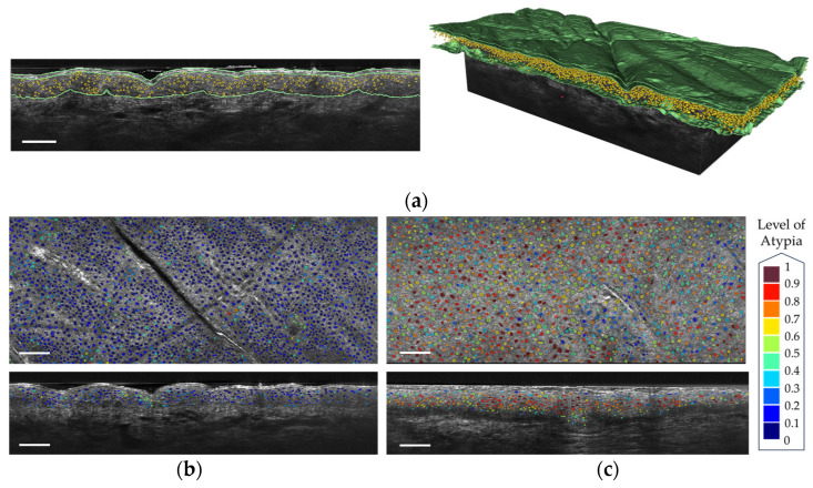
Figure 9
( a ) Segmentation of the keratinocyte nuclei and of the epidermis layers in a vertical LC-OCT image ( left ) and a 3D reconstruction ( right ). ( b ) Segmentation of the keratinocyte nuclei colored a...
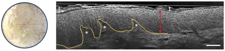
Figure 10
Dermoscopic image ( left ) and vertical sectional LC-OCT image ( right ) of psoriasis. Thickening of the stratum corneum (white arrow with two heads) and of the viable epidermis (red arrow with two he...
Figure images are served from the NIH/NLM PubMed Central Open Access Subset or Europe PMC; copyright remains with the publishers and authors.
💬 Discussion
0 commentsNo comments yet. Be the first to start a discussion!
Leave a Comment