Abstract
AbstractAutomated microscopy can image specimens larger than the microscope’s field of view (FOV) by stitching overlapping image tiles. It also enables time-lapse studies of entire cell cultures in multiple imaging modalities. We created MIST (Microscopy Image Stitching Tool) for rapid and accurate stitching of large 2D time-lapse mosaics. MIST estimates the mechanical stage model parameters (actuator backlash, and stage repeatability ‘r’) from computed pairwise translations and then minimizes stitching errors by optimizing the translations within a (4r)2 square area. MIST has a performance-oriented implementation utilizing multicore hybrid CPU/GPU computing resources, which can process terabytes of time-lapse multi-channel mosaics 15 to 100 times faster than existing tools. We created 15 reference datasets to quantify MIST’s stitching accuracy. The datasets consist of three preparations of stem cell colonies seeded at low density and imaged with varying overlap (10 to 50%). The location and size of 1150 colonies are measured to quantify stitching accuracy. MIST generated stitched images with an average centroid distance error that is less than 2% of a FOV. The sources of these errors include mechanical uncertainties, specimen photobleaching, segmentation, and stitching inaccuracies. MIST produced higher stitching accuracy than three open-source tools. MIST is available in ImageJ at isg.nist.gov.
🧬 Organisms
💻 Software
✨ Fluorophores
🧪 Sample Preparation
🔬 Cell Lines
🏭 Microscope Brands
💻 Software Details
🏛️ Research Organizations (ROR)
Affiliated research institutions:
📋 Methods
Regular stitching algorithms typically consist of three steps: (1) compute candidate translations between adjacent tiles, (2) optimize translations to reduce stitching errors in the mosaic image, and (3) produce the mosaic image based on the translations. Our algorithm introduces an estimation of the microscope mechanical stage parameters as a new step between the steps 1 and 2 if the stage parameters are not provided by the user. MIST uses the stage modeling to perform translation optimization. Translation optimization is needed in experiments with intensity-homogeneous background and sparse foreground objects because of poor signal in overlapping areas. This causes large errors in the estimated tile translations. In addition, translations have a large uncertainty in the relative stage position due to the stage repeatability, that amounts to 1 to 2 microns for good microscopes, and the microscope’s camera angle between the stage coordinate system and the camera coordinate system. The user might specify a desired 10% spatial overlap between consecutive tiles but the actual overlap value could fluctuate between 8% and 12%. This fluctuation is the reason why naïve stitching with fixed overlap will not be accurate. Our method takes advantage of the stage modeling to limit the search space around the 10% value within a range that is proportional to the amount of estimated (or given) stage repeatability. The MIST algorithm consists of the following four steps: (1) compute candidate translations between adjacent tiles, (2) estimate mechanical stage model from computed translations if model parameters are not given by the user, (3) optimize translations to reduce stitching errors in the mosaic image, and (4) compose tiles to produce the mosaic image.
Show full methods section
Regular stitching algorithms typically consist of three steps: (1) compute candidate translations between adjacent tiles, (2) optimize translations to reduce stitching errors in the mosaic image, and (3) produce the mosaic image based on the translations. Our algorithm introduces an estimation of the microscope mechanical stage parameters as a new step between the steps 1 and 2 if the stage parameters are not provided by the user. MIST uses the stage modeling to perform translation optimization. Translation optimization is needed in experiments with intensity-homogeneous background and sparse foreground objects because of poor signal in overlapping areas. This causes large errors in the estimated tile translations. In addition, translations have a large uncertainty in the relative stage position due to the stage repeatability, that amounts to 1 to 2 microns for good microscopes, and the microscope’s camera angle between the stage coordinate system and the camera coordinate system. The user might specify a desired 10% spatial overlap between consecutive tiles but the actual overlap value could fluctuate between 8% and 12%. This fluctuation is the reason why naïve stitching with fixed overlap will not be accurate. Our method takes advantage of the stage modeling to limit the search space around the 10% value within a range that is proportional to the amount of estimated (or given) stage repeatability. The MIST algorithm consists of the following four steps: (1) compute candidate translations between adjacent tiles, (2) estimate mechanical stage model from computed translations if model parameters are not given by the user, (3) optimize translations to reduce stitching errors in the mosaic image, and (4) compose tiles to produce the mosaic image.
Translation computation
MIST uses a Fourier-based approach for simplicity and predictable performance since it does not need an additional feature detection tool. MIST implements the Phase Correlation Method 18 (PCM) to compute translations between adjacent tiles. PCM is based on the Fourier Shift Theorem which computes the spatial shift between two images as a phase shift in the frequency domain. In real images, phase correlation ( PC ) contains several peaks that correspond to different translation values 9 . To determine the correct translation, the top two peaks in the PC matrix are evaluated. The number of peaks is adjustable and the default is two. Due to the periodicity of the Fourier domain, each peak corresponds to four different possible translations (in 2D). We evaluate these four possible translations, for each peak, using the normalized cross-correlation ( ncc ) of the overlap area between adjacent images. The candidate translation with the highest ncc value is selected as the translation between two adjacent images.
Estimation of mechanical stage model from pairwise translations
There is a degree of uncertainty in the translation computation that causes errors in the stitching results. The sources of errors that affect translation computation between pairs of images are: (1) the signal to noise ratio in the acquired image, (2) the amount of signal in the overlap area, (3) the signal distribution with respect to the stage movement in the overlap area (i.e., flat-field effect in some imaging modalities, uniform or periodic signal distribution), and (4) the mechanical imperfections of the automated microscope stage (i.e., stage repeatability and actuator backlash). Moreover, the mechanical stage model parameters vary over time and the variation magnitude depends on the microscope usage. If the microscope’s user calibrated the equipment and measured the stage repeatability, there is an option to input such parameters in the advanced tab of the tool. If the user inputs those parameters, then MIST does not estimate them. However, it is difficult and time consuming to calibrate and estimate the mechanical stage properties of the microscope. Additionally, there are research environments where a microscope might have multiple users. Each user might adjust/change/perturb the camera settings or mechanical stage. These physical changes can alter the microscope to be out of calibration. Finally, there are time-lapse experiments in which touching the mechanical stage cannot be avoided. For example, cells in live experiments need to be fed intermittently. To do this, the sample is removed from the microscope and then put back on the stage after media change. This feeding process can alter the mechanical stage properties among many other experimental settings. Therefore, we are offering an automated way to estimate these stage parameters from the computed translations to prevent the user from having to calibrate and measure these parameters before every acquisition. An automated microscope has two co-planar coordinate frames, the observation frame (i.e., camera) and the control frame (i.e., stage actuators), that are related by the camera angle α , as shown in Fig. 6.a . This angle is difficult to calibrate. Therefore, a misalignment between the camera and stage axes will remain in most experiments. The camera observes the horizontal and vertical stage movements, H and V , as ( H x , H y ) and ( V x , V y ) which are computed as follows: 1 documentclass[12pt]{minimal} usepackage{amsmath} usepackage{wasysym} usepackage{amsfonts} usepackage{amssymb} usepackage{amsbsy} usepackage{mathrsfs} usepackage{upgreek} setlength{oddsidemargin}{-69pt} begin{document}$$[begin{array}{c}{H}_{x}\ {H}_{y}end{array}]=[begin{array}{c}H,cos ,alpha \ -H,sin ,alpha end{array}],{&},[begin{array}{c}{V}_{x}\ {V}_{y}end{array}]=[begin{array}{c}V,sin ,alpha \ V,cos ,alpha end{array}]$$end{document} [ H x H y ] = [ H cos α − H sin α ] & [ V x V y ] = [ V sin α V cos α ] Figure 6 Stage mechanical model. ( a ) Stage displacements as observed by the camera. ( b ) Uncertainty and errors of horizontal and vertical tile translations due to stage mechanical properties. A motorized mechanical XY-Stage moves a biological sample relative to the microscope’s optical column. This movement is carried out by two independent stepper motor linear actuators, one for each direction. The mechanical uncertainty of such a system is known as the stage repeatability. Moreover, the imperfection of the stage as a mechanical device introduces a variable overlap between adjacent tiles. Modeling the mechanical properties of a stage provides an upper bound to the variable overlap and can be used to limit the search for optimal translations, thereby minimizing the margin of stitching error. Figure 6.b shows a grid tiling with the positions ( x , y ) that the stage will visit. Each position has an uncertainty equal to the stage repeatability ( x ± r x , y ± r y ). However, translations ( dx , dy ) computed in the vertical or horizontal directions between adjacent tiles are differences between respective positions. Therefore, the maximum possible error in the computed translation values is ( dx ± 2 r x , dy ± 2 r y ). The horizontal and vertical translations in the image coordinate system must account for the camera angle as well as the mechanical uncertainties. The equations for horizontal and vertical translations that include the microscope models are the following: 2 documentclass[12pt]{minimal} usepackage{amsmath} usepackage{wasysym} usepackage{amsfonts} usepackage{amssymb} usepackage{amsbsy} usepackage{mathrsfs} usepackage{upgreek} setlength{oddsidemargin}{-69pt} begin{document}$${begin{array}{c}{H}_{x}=d{x}_{i},cos (alpha )pm 2{r}_{x}\ {H}_{y}=d{x}_{i},sin (alpha )pm 2{r}_{y}end{array},{rm{and}},{begin{array}{c}{V}_{x}=d{y}_{i},sin (alpha )pm 2{r}_{x}\ {V}_{y}=d{y}_{i},cos (alpha )pm 2{r}_{y}end{array}$$end{document} { H x = d x i cos ( α ) ± 2 r x H y = d x i sin ( α ) ± 2 r y and { V x = d y i sin ( α ) ± 2 r x V y = d y i cos ( α ) ± 2 r y MIST estimates the following four quantities from the translation matrices H and V : (1) overlap amount, (2) the camera angle, (3) the microscope stage repeatability, and (4) the microscope backlash. Supplementary Document section 5 describes the details of this estimation. Translation optimization constrained by stage repeatability Figure 6.b shows each column in H as having the same dx i and the same dy i for each row in V within a ±2 r limit. dx i values differ between the columns of H while dy i values are different between the rows of V due to backlash and mechanical imperfections. As such, we filter H column wise and V row wise where we replace all computed translations, whose dx i or dy i values deviate from the median value by more than 4 × r (the stage repeatability), by the median value in that direction. We then apply Constrained Hill Climbing 19 to the ncc values centered at the median translation and constrained within 4 × r region. Hill climbing will find the translation with the maximum ncc value by following the steepest gradient. The 4 × r constrain comes from the model and bounds the algorithm to a small search space while converging to an optimal value.
Mosaic assembly
The assembly problem can be represented as an undirected graph where vertices are tiles and ncc values are edges. Each tile is connected to its surrounding four neighbors, three neighbors for tiles on edges and two neighbors for tiles on corners. This over-constraint problem needs to be resolved to construct a well-formed image. We use the weighted maximum spanning tree algorithm 20 to find the optimal subset of edges that connects all tiles together, without any circular subsets of edges per tile (each tile is connected only once to the reconstructed image) while maximizing the sum of all weights along that path. The weight of all computed translations that satisfy the physically plausible offset stage model criteria (offsets
📊 Figures

Figure 1
Schematic description of MISTu2019s algorithm summary and novelties.
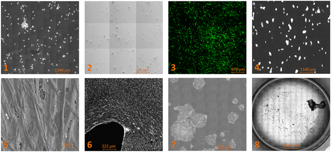
Figure 2
MIST application example images: ( 1 ) A10 cells, ( 2 ) Carbon Nanotubes, ( 3 ) HBMSC, ( 4 ) IPS cell colonies, ( 5 ) Paper nanoparticle, ( 6 ) Rat brain cells, ( 7 ) Stem cell colonies, and ( 8 ) Wor...
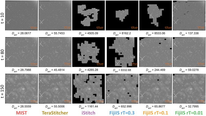
Figure 3
Example of stem cell colonies over time that are stitched by all four tools and with different values of the regression threshold in FijiIS.

Figure 4
( a ) Qualitative stitching accuracy and ( b ) Execution time throughout the time-sequence.

Figure 5
Stitching execution times for varying grid sizes (number of images).

Figure 6
Stage mechanical model. ( a ) Stage displacements as observed by the camera. ( b ) Uncertainty and errors of horizontal and vertical tile translations due to stage mechanical properties.
Figure images are served from the NIH/NLM PubMed Central Open Access Subset or Europe PMC; copyright remains with the publishers and authors.
💬 Discussion
0 commentsNo comments yet. Be the first to start a discussion!
Leave a Comment