Abstract
Understanding and treatment of spinal cord pathology is limited in part by a lack of time-lapse in vivo imaging strategies at the cellular level. We developed a chronically implanted spinal chamber and surgical procedure suitable for time-lapse in vivo multiphoton microscopy of mouse spinal cord without the need for repeat surgical procedures. We routinely imaged mice repeatedly for more than 5 weeks postoperatively with up to ten separate imaging sessions and observed neither motor-function deficit nor neuropathology in the spinal cord as a result of chamber implantation. Using this chamber we quantified microglia and afferent axon dynamics after a laser-induced spinal cord lesion and observed massive microglia infiltration within 1 d along with a heterogeneous dieback of axon stumps. By enabling chronic imaging studies over timescales ranging from minutes to months, our method offers an ideal platform for understanding cellular dynamics in response to injury and therapeutic interventions.
🔬 Techniques
💻 Software
✨ Fluorophores
🧪 Sample Preparation
🔬 Cell Lines
🏭 Microscope Brands
🧪 Reagent Suppliers
🎨 Filters
💻 Software Details
🏛️ Research Organizations (ROR)
Affiliated research institutions:
📋 Methods
Surgical Procedure
We anesthetized mice under 5% isoflurane on a custom-built surgery table ( Supplementary Figure 2 ) and then maintained on ~1.5% isoflurane in 100% oxygen. We injected 0.05 mg of glycopyrrolate (an anticholinergic) per 100-g mouse intramuscularly. We also injected 1 mL per 100-g mouse of 5% glucose in normal saline subcutaneously hourly. We used a rectal thermometer and feedback-controlled heating blanket to maintain body temperature at 37.5 °C. We shaved the dorsal surface above the thoracic spine and applied three alternating washes each of 70% ethanol and iodine to the skin to reduce the likelihood of infection. We gave a subcutaneous injection of 0.1 mL of 0.125% bupivicaine at the site of skin incision. We made a small incision in the skin at the T11-T13 level of the spine and the skin was held back with retractors. We made an incision three-vertebrae long on either side of T12 and scraped the bone clean on the top and the sides. We severed tendons attached to the three vertebrae using surgical scissors. We trimmed all incongruous tissue to reduce necrosis. We used sterile cotton applicators to control bleeding. We clamped the three vertebrae by magnetic stainless steel bars with a notched groove and held under pressure on 30 mm stainless steel posts with a 3-pronged plug, consisting of two pins to prevent rotation and a central magnet to hold the bar. We removed the dorsal lamina of T12 using vanna scissors, and used sterile gel foam (Pharmacia & Upjohn Co.) or cotton applicators along with sterile saline to control bleeding and keep blood off the surface of the cord. We trimmed the lateral edges of the bone back as close as possible to the edges of the bars and the surface of the bone sealed with dental acrylic and cyanoacrylate. Where possible, we left the dura intact. Keeping the cord irrigated with normal saline, we positioned a top plate and screws inserted into the metal bars. We injected Kwik-Sil® silicone elastomer into the space between the cord and the top plate and sealed the chamber with a 5-mm diameter coverslip. We used cyanoacrylate glue and dental acrylic to seal the chamber at the rostral and caudal vertebrae. With pressure maintained by the screws, we removed the 3-pronged steel posts. We pulsed the skin to the edge of the implant and secured it with cyanoacrylate glue and dental acrylic. We inserted setscrews into the wings of the top plate. An illustration of the procedure with accompanying photographs is given in Supplementary Figure 1 . We again injected bupivicaine (0.1 mL, 0.125%) around the edge of the implant. During recovery, we placed the animal on a heated surface, and administered ketoprofen (5 mg/kg/day) and dexamethasone (0.2 mg/kg/day) every 24 hours for 72 hours. A detailed, step-by-step description of how to perform the procedure, with suggested solutions to common problems, is provided in the Supplementary Protocol . We performed all surgery under a stereomicroscope (Leica MZ12.5; Leica Microsystems). All animal procedures performed have the approval of the Cornell Institutional Animal Care and Use Committee (IACUC) and under the guidance of the Cornell Center for Animal Resources and Education.
Show full methods section
Surgical Procedure
We anesthetized mice under 5% isoflurane on a custom-built surgery table ( Supplementary Figure 2 ) and then maintained on ~1.5% isoflurane in 100% oxygen. We injected 0.05 mg of glycopyrrolate (an anticholinergic) per 100-g mouse intramuscularly. We also injected 1 mL per 100-g mouse of 5% glucose in normal saline subcutaneously hourly. We used a rectal thermometer and feedback-controlled heating blanket to maintain body temperature at 37.5 °C. We shaved the dorsal surface above the thoracic spine and applied three alternating washes each of 70% ethanol and iodine to the skin to reduce the likelihood of infection. We gave a subcutaneous injection of 0.1 mL of 0.125% bupivicaine at the site of skin incision. We made a small incision in the skin at the T11-T13 level of the spine and the skin was held back with retractors. We made an incision three-vertebrae long on either side of T12 and scraped the bone clean on the top and the sides. We severed tendons attached to the three vertebrae using surgical scissors. We trimmed all incongruous tissue to reduce necrosis. We used sterile cotton applicators to control bleeding. We clamped the three vertebrae by magnetic stainless steel bars with a notched groove and held under pressure on 30 mm stainless steel posts with a 3-pronged plug, consisting of two pins to prevent rotation and a central magnet to hold the bar. We removed the dorsal lamina of T12 using vanna scissors, and used sterile gel foam (Pharmacia & Upjohn Co.) or cotton applicators along with sterile saline to control bleeding and keep blood off the surface of the cord. We trimmed the lateral edges of the bone back as close as possible to the edges of the bars and the surface of the bone sealed with dental acrylic and cyanoacrylate. Where possible, we left the dura intact. Keeping the cord irrigated with normal saline, we positioned a top plate and screws inserted into the metal bars. We injected Kwik-Sil® silicone elastomer into the space between the cord and the top plate and sealed the chamber with a 5-mm diameter coverslip. We used cyanoacrylate glue and dental acrylic to seal the chamber at the rostral and caudal vertebrae. With pressure maintained by the screws, we removed the 3-pronged steel posts. We pulsed the skin to the edge of the implant and secured it with cyanoacrylate glue and dental acrylic. We inserted setscrews into the wings of the top plate. An illustration of the procedure with accompanying photographs is given in Supplementary Figure 1 . We again injected bupivicaine (0.1 mL, 0.125%) around the edge of the implant. During recovery, we placed the animal on a heated surface, and administered ketoprofen (5 mg/kg/day) and dexamethasone (0.2 mg/kg/day) every 24 hours for 72 hours. A detailed, step-by-step description of how to perform the procedure, with suggested solutions to common problems, is provided in the Supplementary Protocol . We performed all surgery under a stereomicroscope (Leica MZ12.5; Leica Microsystems). All animal procedures performed have the approval of the Cornell Institutional Animal Care and Use Committee (IACUC) and under the guidance of the Cornell Center for Animal Resources and Education.
Mice
For imaging purposes, we used mice of the YFP-H line (Jackson Labs), which expresses YFP in a subset of pyramidal neurons and dorsal root ganglia. In addition we used CX 3 CR1-GFP mice (Jackson Labs), which express GFP in microglia. We also used crosses between the YFP-H and CX 3 CR1-GFP lines. For histopathological analysis, we used mice of the YFP-H line and mice of the Emx-1-cre (Jackson Labs) lines. We used CX 3 CR1-GFP mice and GFAP-GFP (Jackson labs), which express GFP in astrocytes, to study reactive gliosis in microglia and astrocytes, respectively. In all cases, mice were of both sexes and 4 to 8 months in age when the device was implanted and they were heterozygous for each transgene. Mice were group housed prior to chamber implantation and were singly housed in rat-size cages after implantation to minimize the risk of the animal bumping the implanted chamber against the cage lid.
Histology
We deeply anesthetized mice and perfused transcardially with phosphate buffered saline (PBS) (Sigma-Aldrich) to clear the blood, followed by fixation with 4% paraformaldehyde (PFA) (ThermoFisher Scientific) in PBS. For gliosis studies in GFAP-GFP and CX 3 CR1-GFP mice, we immersed whole spines in PFA for one day post-perfusion followed by removal of the spinal cord from the vertebral canal by microsurgical dissection. We immersed dissected spinal cords in 30% sucrose in PBS until saturated. We froze spinal cords in optimal cutting temperature (OCT) compound (Tissue-Tek) and cut sections at a nominal thickness of 30 μm on a Microm HM550 cryotome (ThermoFisher Scientific). We took sections at the rostral and caudal edges of the implant, underneath the glass, and control regions located one vertebrae in the rostral and caudal direction from the edges of the implant. We examined tissues under an Olympus BX41 wide-field fluorescence microscope (Olympus America). For hematoxylin and eosin (H&E) histopathology studies, we examined whole fixed mice for gross pathology and the skin surrounding the chambers was gently freed and removed. We separated the chambers from their attachment to the subjacent vertebral bodies starting at one end by gentle dorsal traction. Once freed from the vertebral bodies, we carefully separated the chambers from subjacent soft tissues (epaxial muscle and connective tissues). We removed any material (mostly injected silicone) that had adhered to the ventral surface of the glass windows using a scalpel and reserved it for staining. After removing ribs and organs from the vertebral column, we collected 3-mm cross sections of the vertebral column–including surrounding muscle–from approximately 1 cm rostral, 1 cm caudal and directly below the center of the window by making cuts perpendicular to the vertebral column using a broad tissue blade. We inserted tissues into cassettes and immersed them again in PFA. We decalcified tissues by rinsing tissue cassettes under running water for 15 minutes, followed by placement in a vacuum jar containing equal volumes of 20% sodium citrate dihydrate and 50% formic acid. Tissues were held under vacuum at room temperature with constant stirring using a magnet for approximately 24 hours. Following this procedure, we rinsed tissues under running water for 10 minutes and put in a solution of 70% ethyl alcohol. We then embedded tissues in paraffin wax using an automated tissue processor (Tissue-Tek VIP), sectioned (4-μm thick sections), and stained them with H&E using an automated stainer (Shandon Varistain 24-4; Thermo Scientific, Waltham, MA). We sealed slides with a cover slip and examined using an Olympus BX40 microscope (Olympus America).
2PEF Microscopy
To image (or reimage) the spinal cord, we anesthetized mice with isoflurane and placed on the custom-surgery table described previously for the laminectomy procedure. Mice also received glycopyrrolate and glucose as described above. We used tapped 30-mm posts secured in an optical post holder to screw finger-tight onto the set screws of the wings of the top plate of the implant to locally immobilize the spine ( Supplementary Figure 1g ). We elevated mice slightly by the implant to allow room for chest expansion and contraction during breathing. After imaging, we twisted off the posts and the animal was allowed to recover on a heated surface. We performed imaging using a custom-designed multiphoton microscope with a 20x water immersion objective lens (NA = 1.0; Carl Zeiss MicroImaging, Inc.), a 40x water immersion objective (NA = 0.8; Olympus America), or a 4x objective (NA = 0.28; Olympus). We performed 2PEF imaging using 1043-nm wavelength, 1-MHz, 300-fs pulses from a fiber laser (FCPA μJewel D-400; IMRA America, Inc) and/or 920-nm, 87-MHz, 100-fs pulses from a Ti:Sapphire laser oscillator (MIRA HP; Coherent). We used emission filters at 645/65 nm (center wavelength/bandwidth), 550/50 nm, and 517/65 nm (Chroma Technology) to isolate fluorescence from Texas Red dextran, YFP, and GFP, respectively. Spinal cord lesioning We made lesions measuring 100–300-μm long, 5–10-μm wide and 30–40-μm deep in the dorsal spinal cord by femtosecond laser ablation using ~100-nJ pulses from a regenerative amplifier (800-nm wavelength, 50-fs pulse duration, 1-kHz repetition rate; Legend, Coherent Inc.). We used custom software in MATLAB (MathWorks) to define a two-dimensional trajectory by tracing a pattern on a z -projection of a 3D image stack. To minimize the loss of image contrast caused by excessive bleeding, we intentionally avoided cutting blood vessels where possible. To execute the pattern, the animal was translated at 500 μm/s along the traced trajectory in the xy -plane while a shutter controlling the femtosecond pulses was opened, producing a cut about 2-3 μm deep. The animal was then translated by 1 μm in the z -direction and the cut pattern was repeated. This procedure was iterated until a cut depth of 30–40 μm was achieved. The shutter was closed during translation in z . When deemed necessary, we repeated the cut to ensure complete transection of axons. Because the damage is mediated by an electron-ion plasma formed by nonlinear optical absorption and there is very little thermal energy deposited, the damage is largely confined to the focal volume.
Image Processing
We computed image projections by taking the standard deviation along the z -axis of three-dimensional image stacks. For contrast and resolution measurements, we used maximum pixel intensity projections of isolated axon segments. Since we oversampled image stacks, we manually removed frames with significant motion artifact due to breathing without loss of information. Due to the high density of microglia observed after SCI, there was ambiguity in distinguishing cell bodies from densely packed processes. We manually identified microglia cell bodies as fluorescent ameboid structures with visible boundaries, traced, and counted them in 2-D projections using custom MATLAB software. We defined microglia scar size as the mean square radius in manual traces of the boundary of the largest contiguous aggregate of microglia. For axon tracing, we Fourier filtered high-resolution (0.59 μm/pixel) 3-D image stacks, took the standard deviation projection, and stitched the images together using PanaVue stitching software (PanaVue). We used spared axons that were stable over the duration of the experiments to define a common point of origin among imaging sessions. We marked axon endings and tracked them using custom software in MATLAB. We resolved ambiguities by examining trajectories in the 3-D stacks. In double-transgenic mice expressing YFP in axons and GFP in microglia, we used emission filters with 517/65 nm and 550/50 nm (center wavelength/bandwidth) with 920-nm excitation for 2PEF imaging. We linearly unmixed images in custom software written in MATLAB. Briefly, we manually selected image features corresponding to axons (YFP) or microglia (GFP) in both imaging channels and generated a mixing matrix. We then solved for the inverse matrix, and calculated the resultant unmixed images containing separate fluorescent species.
Contrast and resolution fitting
To characterize the contrast and resolution, we first used ImageJ to isolate axon segments of approximately 40-50 μm in length from image stacks the same region across multiple days. We performed subsequent analysis in MATLAB. We computed the maximum projection along the z -axis and median filtered the resulting image with a 1-pixel filter radius. To orient the segment so that the axis ran parallel to the y -axis, we used a radon transform to find the angle of orientation and the image was rotated accordingly. Since we considered the maximum intensity projection across the axon volume, the intensity profile is equal to the value of the intensity profile taken immediately through the center of the axon, where, to good approximation, the excited fluorescence within the axon is approximately constant in the x -direction. For an axon of radius R , and displaced from the origin by an amount δ, the fluorophore concentration profile, C , in a single scan at the center is: (S1) C ( x ) = C 0 [ θ ( x + R + δ ) − θ ( x − R + δ ) ] where C 0 is the axonal fluorophore concentration and θ(x) is the Heaviside step function. For a Gaussian excitation beam with intensity profile: (S2) I ( x ) = I 0 exp ( − x 2 2 a 2 ) where I 0 is the peak laser intensity and a is a measure of the beam waist, the image intensity, F ( x ), is given by the convolution of Equation S1 and S2 with the addition of a background noise floor, B : (S3) F ( x ) = A [ erf ( x + R + δ 2 a ) − erf ( x − R + δ 2 a ) ] + B where (S4) A = π 2 aI 0 C 0 We fit Equation (S3) to each line of the axon profile (see Fig. 2c ) and averaged the results. Failure to converge by nonlinear least squares fitting or an R 2 value less than 0.85 was used to exclude data points. We defined contrast as: (S5) F ( − δ ) − B F ( − δ ) + B which ranges between 0 (no contrast) and 1 (noiseless contrast), where F (- δ ) is the intensity peak in the axon. We took resolution as the parameter a .
Behavioral Assays
We subjected mice to open field and runway assays. We first made measurements one day prior to implantation of an imaging window, followed by measurements each day for the first seven days and a final time point at 14 days post-implantation. We made all measurements at the same time of day to avoid circadian variability. We tested animals that were shaved and anesthetized, but not operated on, simultaneously as sham controls. We constructed analysis of footprints from the runway assay in which mice with inked paws traversed the length of a Plexiglass enclosure (76 cm long x 8 cm wide x 20 cm high) to enter a dark goal box at the end of the runway. We placed mice on an inked pad in a 15 cm long staging area separated from the main runway by a sliding insert. We placed paper tape on the floor of the runway to collect ink pawprints. Removal of the insert marked the beginning of the trial. All trials were video recorded from above. We performed three trials at each time point, and took footprint measurements from 5 consecutive steps in each trial. We then returned mice to their home cage between trials to minimize the effects of fatigue. Mice received 10-14 days of behavioral training prior to surgery. During training, we encouraged mice to traverse the length of the runway without pausing, receiving prompting from the experimenter where necessary. We deemed training complete when mice traversed the length of the runway without pausing or prompting. We assessed hindlimb base of support as the lateral distance between hindlimbs, and stride length as the distance between the central pads of two consecutive hindlimb prints on the left or right. We determined average speed by dividing the runway length by the total time of the trial, as determined by the video clock. We assessed rearing, grooming, mobility and top speeds in open field measurements. We placed mice in the center of a Plexiglass enclosure (46 cm long x 46 cm wide x 47 cm high) with black sides and a white base. We recorded mice from above for 5 minutes under red light illumination. Video tracking analysis was performed based on the videos using ANY-maze software (Stoelting Company) and MATLAB. We defined rearing as any period during which the animal lifted both of its forelimbs off the ground simultaneously. We defined grooming as any period during which the animal licked its fur or moved its forelimbs over the head. Top speeds were determined as the mean of the speeds greater than the 75 th percentile.
Statistical Analysis
We compared grooming time, time spent immobile, rearing time, base of support, stride length and average speed using the analysis of variance (ANOVA) test. Where the null hypothesis was rejected, we performed post hoc analyses using Tukey’s honestly significant difference for pairwise comparisons. We compared top speeds of mice receiving surgery and shams each day using a Mann-Whitney-U test. We compared microglia and astrocyte densities using ANOVA. Where the null hypothesis was rejected, we performed post hoc analyses using Tukey’s honestly significant difference on mean to compare groups. We performed statistical tests in Kaelidograph (Synergy) and MATLAB. We set the criterion for significance in all cases to be α = 0.05.
Surgical Procedure
We anesthetized mice under 5% isoflurane on a custom-built surgery table ( Supplementary Figure 2 ) and then maintained on ~1.5% isoflurane in 100% oxygen. We injected 0.05 mg of glycopyrrolate (an anticholinergic) per 100-g mouse intramuscularly. We also injected 1 mL per 100-g mouse of 5% glucose in normal saline subcutaneously hourly. We used a rectal thermometer and feedback-controlled heating blanket to maintain body temperature at 37.5 °C. We shaved the dorsal surface above the thoracic spine and applied three alternating washes each of 70% ethanol and iodine to the skin to reduce the likelihood of infection. We gave a subcutaneous injection of 0.1 mL of 0.125% bupivicaine at the site of skin incision. We made a small incision in the skin at the T11-T13 level of the spine and the skin was held back with retractors. We made an incision three-vertebrae long on either side of T12 and scraped the bone clean on the top and the sides. We severed tendons attached to the three vertebrae using surgical scissors. We trimmed all incongruous tissue to reduce necrosis. We used sterile cotton applicators to control bleeding. We clamped the three vertebrae by magnetic stainless steel bars with a notched groove and held under pressure on 30 mm stainless steel posts with a 3-pronged plug, consisting of two pins to prevent rotation and a central magnet to hold the bar. We removed the dorsal lamina of T12 using vanna scissors, and used sterile gel foam (Pharmacia & Upjohn Co.) or cotton applicators along with sterile saline to control bleeding and keep blood off the surface of the cord. We trimmed the lateral edges of the bone back as close as possible to the edges of the bars and the surface of the bone sealed with dental acrylic and cyanoacrylate. Where possible, we left the dura intact. Keeping the cord irrigated with normal saline, we positioned a top plate and screws inserted into the metal bars. We injected Kwik-Sil® silicone elastomer into the space between the cord and the top plate and sealed the chamber with a 5-mm diameter coverslip. We used cyanoacrylate glue and dental acrylic to seal the chamber at the rostral and caudal vertebrae. With pressure maintained by the screws, we removed the 3-pronged steel posts. We pulsed the skin to the edge of the implant and secured it with cyanoacrylate glue and dental acrylic. We inserted setscrews into the wings of the top plate. An illustration of the procedure with accompanying photographs is given in Supplementary Figure 1 . We again injected bupivicaine (0.1 mL, 0.125%) around the edge of the implant. During recovery, we placed the animal on a heated surface, and administered ketoprofen (5 mg/kg/day) and dexamethasone (0.2 mg/kg/day) every 24 hours for 72 hours. A detailed, step-by-step description of how to perform the procedure, with suggested solutions to common problems, is provided in the Supplementary Protocol . We performed all surgery under a stereomicroscope (Leica MZ12.5; Leica Microsystems). All animal procedures performed have the approval of the Cornell Institutional Animal Care and Use Committee (IACUC) and under the guidance of the Cornell Center for Animal Resources and Education.
Supplementary Material 1 video 1 video 2 video 3
📊 Figures
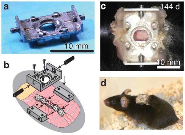
Figure 1
An imaging chamber for longitudinal optical access to mouse spinal cord without the need for repeated surgeries
(a) Photograph of the imaging chamber. Scale bar, 10 mm. (b) Schema showing the implantation of the imaging chamber in mice at the T11-T12 vertebra, just below the dorsal fat pad (taupe). (c) , Photog...
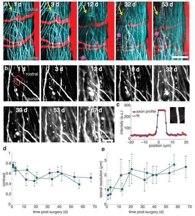
Figure 2
Longitudinal 2PEF imaging of axons and blood vessels over many weeks post-surgery
( a ) Projections of 2PEF image stacks of afferent axons expressing YFP (teal) and blood vessels labeled with intravenously-injected Texas Red dextran (red) taken over nine weeks after chamber implant...
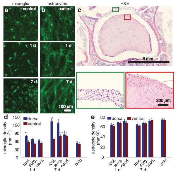
Figure 3
Histological analysis of reactive microglia and astrocytes, and tissue morphology after chamber implantation
(a,b) Wide-field fluorescence images of 30 u03bcm-thick coronal tissue sections from the laminectomy site and adjacent vertebral segments one day and one week after implantation and in control animals...
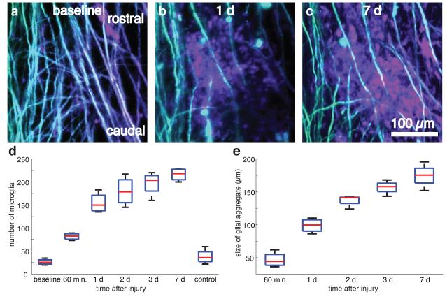
Figure 4
Imaging and quantification of microglial scar formation at the site of a laser-induced spinal cord injury
(a.b) Projections of 2PEF image stacks of YFP-labeled axons (teal) and GFP-labeled microglia (mauve) before( a ), one day ( b ), and one week ( c ) after producing a ~200-u03bcm long laser-induced mic...
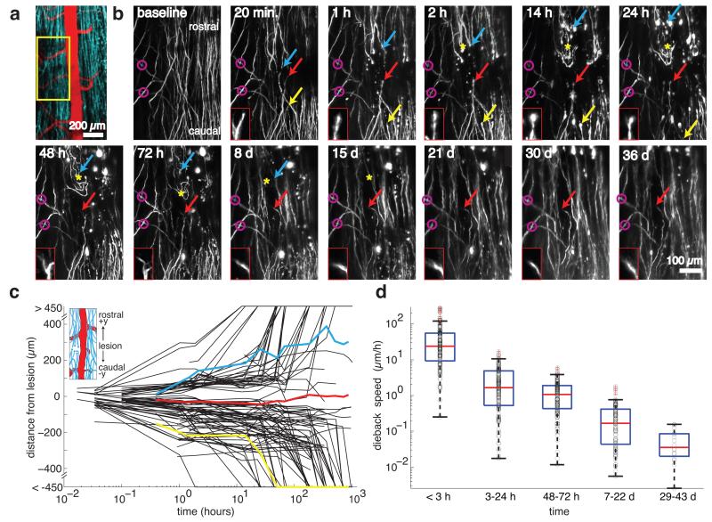
Figure 5
2PEF imaging and quantification of axon dieback after a laser-induced spinal cord injury
( a ) Projection of a 2PEF image stack from mice expressing YFP (teal) in a subset of DRGs with the vasculature labeled with Texas Red dextran (red). The yellow box denotes the location of the high-re...
Figure images are served from the NIH/NLM PubMed Central Open Access Subset or Europe PMC; copyright remains with the publishers and authors.
💬 Discussion
0 commentsNo comments yet. Be the first to start a discussion!
Leave a Comment