Abstract
Purpose. To evaluate and compare corneal backscatter from anterior stroma between small incision lenticule extraction (SMILE) and femtosecond laser-assisted LASIK (femto-LASIK). Methods. A cohort of 60 eyes of 30 patients was randomized to receive SMILE in one eye and femto-LASIK in the fellow eye. In vivo confocal microscopy was performed at 1 week and 1, 3, and 6 months after surgery. The main outcome measurements were maximum backscattered intensity and the depth from which it was measured, the backscattered light intensity 30 μ m below Bowman's membrane at the flap interface and 150 μ m below the superficial epithelium, and the number of refractive particles at the flap interface. Results. The mean backscattered light intensity (LI) at all measured depths and the maximum backscattered LI were higher in the SMILE group than the femto-LASIK group at all postoperative visits. LI differences at 1 week and 1- and 3-month visits were statistically significant (P < 0,05). LI differences at 6 months were not statistically significant. There was no difference in the number of refractive particles at the flap interface between the groups at any visit. Conclusions. SMILE results in increased backscattered LI in the anterior stroma when compared with femto-LASIK were evaluated.
🔬 Techniques
🧪 Sample Preparation
🏭 Microscope Brands
💻 Software Details
🏛️ Research Organizations (ROR)
Affiliated research institutions:
📋 Methods
2.
Patients and Methods
This prospective study was approved by the ethics committee of the Beyoglu Eye Research and Training Hospital and adheres to the principles of the Declaration of Helsinki. All patients provided informed consent. The study enrolled patients older than 18 years old with myopia or myopic astigmatism with a spherical equivalent refraction of 300 μ m. Other inclusion criteria were best corrected visual acuity of at least 20/25 in both eyes, no ocular disease other than the refractive error, a normal topographic pattern and regular retinoscopic reflex, corneal pachymetry of >500 μ m at the thinnest point, and stable refraction for at least 2 years. 2.1. Preoperative and Postoperative Examinations All patients underwent the standard preoperative refractive surgery procedures of the clinic. All visual acuity measurements were completed using an illuminated ETDRS chart (Optec 3500 Vision Tester, Stereo Optical Co., USA). Objective cycloplegic refraction was performed with an autorefractometer (KR-1 Auto Kerato-Refractometer, Topcon, Japan) and retinoscopy in all patients. Corneal topography, dynamic infrared pupillography, ocular wavefront analysis, and corneal wavefront analysis were performed with a Sirius corneal topography and abberometry system (Costruzioni Strumenti Oftalmici, Italy). Horizontal corneal diameter was measured with an IOLMaster 500 (Carl Zeiss Meditec, Germany). Intraocular pressure was measured with a Goldmann applanation tonometer. All patients underwent a detailed anterior and posterior segment examination using a slit lamp. Optical coherence tomography was performed at the 1-month followup to evaluate flap and cap thicknesses. 2.2. Patient Randomization One eye of each patient was assigned to the SMILE group and the fellow eye to the femto-LASIK group using a random number table. The random numbers were placed in sealed envelopes that were shuffled and then sequentially numbered. The surgeon opened the next available envelope before the surgery. If the random number in the envelope was odd, then the right eye was allocated to the SMILE group, and if the number was even, the left eye was allocated to the SMILE group. 2.3. Surgical Technique The same surgeon (A. Demriok) performed all eye surgeries in the study. For each patient, surgery was performed on both eyes on the same day. The eye in the SMILE group was treated first. The flap of the fellow eye was created before transporting the patient to the excimer laser. 2.4. SMILE A VisuMax (Carl Zeiss Meditec, Germany) femtosecond laser platform was used for all eye surgeries. The same parameters were used in all cases. The spot distance was 3 μ m for lamellar cuts and 2 μ m for side cuts. The spot energy was set to 140 nJ. The minimum lenticule side cut thickness was set to 15 μ m. The lenticule side cut angle was 120°, and the optical zone was 6.5 mm. The optical zone diameter was equal to the lenticule diameter in patients with purely spherical refractive error. However, if the patient had astigmatism, the software added a transition zone to convert the oval lenticule into a circle. As a result, the lenticule diameter was 6.5-6.6 mm depending on the presence or absence of astigmatism. The cap diameter was 7.5 mm with a 50° superior side cut and a side cut angle of 90°. A small-sized (Size S) patient interface was used in all patients. When the lenticule and side cut had been created, the surgeon positioned the eye under the operating microscope of the laser platform using the joystick. Under the operating microscope, a blunt spatula was inserted into the anterior lamellar photodisruption plane to perform dissection of any remaining attachments. The same maneuver was performed in the posterior lamellar photodisruption plane. After the lenticule was completely dissected from the overlying and underlying stroma, it was extracted through the side cut with forceps. An antibiotic drop was applied at the end of the operation. 2.5. Femto-LASIK After one drop of topical anesthetic was applied to both eyes and sterile draping was placed, an eyelid speculum was inserted. Flaps were created by a VisuMax femtosecond laser platform (Carl Zeiss Meditec, Germany). Spot energy was set to 140 nJ. Spot distance was 3 μ m for the lamellar flap cut and 2 μ m for the flap side cut. The flap side cut was 90°, and the flap diameter was set to 8.5 mm in all patients. A medium-sized (Size M) patient interface was used in all patients. After the flap was created, the patient was transported to a Schwind Amaris 750S (SCHWIND eye-tech solutions, Germany) excimer laser platform. The flap was lifted with a blunt spatula (Katena, USA), and excimer laser photoablation was performed. The residual stromal bed was washed with balanced salt solution, and the flap was repositioned. An antibiotic drop was applied at the end of the operation. 2.6.
Show full methods section
2.
Patients and Methods
This prospective study was approved by the ethics committee of the Beyoglu Eye Research and Training Hospital and adheres to the principles of the Declaration of Helsinki. All patients provided informed consent. The study enrolled patients older than 18 years old with myopia or myopic astigmatism with a spherical equivalent refraction of 300 μ m. Other inclusion criteria were best corrected visual acuity of at least 20/25 in both eyes, no ocular disease other than the refractive error, a normal topographic pattern and regular retinoscopic reflex, corneal pachymetry of >500 μ m at the thinnest point, and stable refraction for at least 2 years. 2.1. Preoperative and Postoperative Examinations All patients underwent the standard preoperative refractive surgery procedures of the clinic. All visual acuity measurements were completed using an illuminated ETDRS chart (Optec 3500 Vision Tester, Stereo Optical Co., USA). Objective cycloplegic refraction was performed with an autorefractometer (KR-1 Auto Kerato-Refractometer, Topcon, Japan) and retinoscopy in all patients. Corneal topography, dynamic infrared pupillography, ocular wavefront analysis, and corneal wavefront analysis were performed with a Sirius corneal topography and abberometry system (Costruzioni Strumenti Oftalmici, Italy). Horizontal corneal diameter was measured with an IOLMaster 500 (Carl Zeiss Meditec, Germany). Intraocular pressure was measured with a Goldmann applanation tonometer. All patients underwent a detailed anterior and posterior segment examination using a slit lamp. Optical coherence tomography was performed at the 1-month followup to evaluate flap and cap thicknesses. 2.2. Patient Randomization One eye of each patient was assigned to the SMILE group and the fellow eye to the femto-LASIK group using a random number table. The random numbers were placed in sealed envelopes that were shuffled and then sequentially numbered. The surgeon opened the next available envelope before the surgery. If the random number in the envelope was odd, then the right eye was allocated to the SMILE group, and if the number was even, the left eye was allocated to the SMILE group. 2.3. Surgical Technique The same surgeon (A. Demriok) performed all eye surgeries in the study. For each patient, surgery was performed on both eyes on the same day. The eye in the SMILE group was treated first. The flap of the fellow eye was created before transporting the patient to the excimer laser. 2.4. SMILE A VisuMax (Carl Zeiss Meditec, Germany) femtosecond laser platform was used for all eye surgeries. The same parameters were used in all cases. The spot distance was 3 μ m for lamellar cuts and 2 μ m for side cuts. The spot energy was set to 140 nJ. The minimum lenticule side cut thickness was set to 15 μ m. The lenticule side cut angle was 120°, and the optical zone was 6.5 mm. The optical zone diameter was equal to the lenticule diameter in patients with purely spherical refractive error. However, if the patient had astigmatism, the software added a transition zone to convert the oval lenticule into a circle. As a result, the lenticule diameter was 6.5-6.6 mm depending on the presence or absence of astigmatism. The cap diameter was 7.5 mm with a 50° superior side cut and a side cut angle of 90°. A small-sized (Size S) patient interface was used in all patients. When the lenticule and side cut had been created, the surgeon positioned the eye under the operating microscope of the laser platform using the joystick. Under the operating microscope, a blunt spatula was inserted into the anterior lamellar photodisruption plane to perform dissection of any remaining attachments. The same maneuver was performed in the posterior lamellar photodisruption plane. After the lenticule was completely dissected from the overlying and underlying stroma, it was extracted through the side cut with forceps. An antibiotic drop was applied at the end of the operation. 2.5. Femto-LASIK After one drop of topical anesthetic was applied to both eyes and sterile draping was placed, an eyelid speculum was inserted. Flaps were created by a VisuMax femtosecond laser platform (Carl Zeiss Meditec, Germany). Spot energy was set to 140 nJ. Spot distance was 3 μ m for the lamellar flap cut and 2 μ m for the flap side cut. The flap side cut was 90°, and the flap diameter was set to 8.5 mm in all patients. A medium-sized (Size M) patient interface was used in all patients. After the flap was created, the patient was transported to a Schwind Amaris 750S (SCHWIND eye-tech solutions, Germany) excimer laser platform. The flap was lifted with a blunt spatula (Katena, USA), and excimer laser photoablation was performed. The residual stromal bed was washed with balanced salt solution, and the flap was repositioned. An antibiotic drop was applied at the end of the operation. 2.6.
Confocal Microscopy
Confocal microscopy (Confoscan 4, Nidek, Italy) was performed at week 1 and months 1, 3, and 6. The same experienced technician (A. Agca), who had no involvement in the operative procedures, performed all the examinations. The device was equipped with a standard ×40 water-immersion front lens and a Z-ring. One drop of Viscotears (Novartis Pharma AG, Basel, Switzerland) was applied as an immersion substance between the ×40 objective lens and the Z-ring before each examination. A sterile small wire-lid speculum was inserted into the patient's eye after topical anesthesia to improve examination quality. The technician asked the patient to look at the internal fixation light and manually centered on the endothelium before activating the microscope's autoalignment. The device was used in full-thickness mode. The images were immediately reviewed by the technician and the first author. The procedure was repeated if there were any concerns about the quality or centration of the images or the stability of centration and quality throughout the image acquisition period. The backscattered LI measurements were standardized by using Amco Clear turbidity standard (GFS Chemicals Inc., USA) and presented in scatter units as previously described [ 11 ]. Turbidity is measured in nephelometric turbidity units (NTU). The relation between turbidity and image intensity can be used to express image intensity in SUs, provided that 1 SU is equal to the image intensity measured in a 1-NTU suspension [ 10 – 12 ]. AMCO clear is a commercially available calibration standard for measuring turbidity. In our study, we examined AC-4000 (AMCO Clear in a maximum concentration equivalent to 4000 NTU) through a transparent rectangular 10 mm sample cell (LPZ045; Hach Lange, Tiel, The Netherlands) and then, after gradual dilution, AC-2000, AC-1000, and AC-500. Hillenaar et al. showed that the relation between image intensity and turbidity depends on the imaging depth and that a linear relationship with turbidity only exists at a depth image intensity of 200 μ m [ 11 ]. Thus, the image intensities at a depth of 200 μ m were plotted against the turbidity values, and the linear function defining the relation between them was used as the standardization function. This calculation was performed only once (at the beginning of the study) to define a standardization function that could be used to convert the ConfoScan 4 raw image intensity data to SU. To ensure standardization of backscatter measurements over a long time period, a polymethylmethacrylate slab (PMMA, Opal 040 Perspex GS; Lucite International Ltd., UK) was used every week [ 11 , 12 ]. During pre- and postoperative visits, backscattered LI was measured at the flap/cap interface, at the flap/cap-stromal bed interface, and at the stromal bed. In postoperative visits, the peak backscattered LI in the anterior stroma and its corresponding corneal depth were also recorded. The border of the anterior stroma was determined as described by Hillenaar et al. [ 12 ]. In addition, the reflective particles at the flap/cap interface were counted manually. 2.7. Flap and Cap Tissues A backscattered LI value was recorded 30 μ m below Bowman's membrane as this location approximately represents the middle portion of the flap or cap stroma in a 120 μ m flap or cap. 2.8. Flap/Cap-Stromal Bed Interface The interface was identified by the presence of refractive particles. The image with the clearest view of the refractive particles was selected to represent the flap/cap-stromal bed interface. The intended flap and cap thicknesses were 120 μ m in all eyes. Accordingly, if it was difficult to choose between two images, the one that was nearest to 120 μ m from the last focused corneal epithelium image was chosen. 2.9. Stromal Bed Corneal stroma 150 μ m below the superficial epithelium was chosen to represent the stromal bed, just below the stromal interface. 2.10.
Statistical Analysis
The distributions of variables were determined with Kolmogorov-Smirnov tests. The mean, standard deviation, and frequency were used in the statistical analysis. The preoperative data were compared using Student's t -test ( Table 1 ). The preoperative and postoperative data were analyzed using two-way repeated measure ANOVA with post hoc multiple comparisons. IBM SPSS 20.0 (IBM Corporation, USA) software was used to analyze the data.
📊 Figures
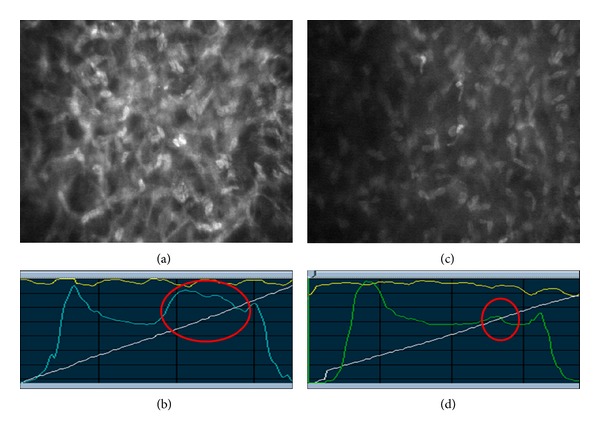
Figure 1
Fellow eyes of the same patient 1 week after surgery. (a) Activated keratocytes (at 150 u03bc m depth) organized as a network after SMILE surgery. (b) Anterior stroma of the same eye shows dramaticall...
Figure images are served from the NIH/NLM PubMed Central Open Access Subset or Europe PMC; copyright remains with the publishers and authors.
💬 Discussion
0 commentsNo comments yet. Be the first to start a discussion!
Leave a Comment