Abstract
The spectral dispersion of ultrashort pulses allows the simultaneous focusing of light in both space and time, which creates so-called spatiotemporal foci. Such space-time coupling may be combined with the existing holographic techniques to give a further dimension of control when generating focal light fields. In the present study, it is shown that a phase-only hologram placed in the pupil plane of an objective and illuminated by a spatially chirped ultrashort pulse can be used to generate three-dimensional arrays of spatio-temporally focused spots. By exploiting the pulse front tilt generated at focus when applying simultaneous spatial and temporal focusing (SSTF), it is possible to overlap neighboring foci in time to create a smooth intensity distribution. The resulting light field displays a high level of axial confinement, with experimental demonstrations given through two-photon microscopy and the non-linear laser fabrication of glass.
🔬 Techniques
✨ Fluorophores
🧪 Sample Preparation
🏭 Microscope Brands
🧪 Reagent Suppliers
📷 Detectors
🏛️ Research Organizations (ROR)
Affiliated research institutions:
📋 Methods
Holography in a spatially chirped beam How can holographic elements be used to adjust the focus in the time dimension? It is already known that applying group velocity dispersion (GVD) to an ultrafast beam axially scans an SSTF focus 31 . This can be simply understood if the GVD corresponds to a quadratic spectral phase (that is, the phase shift ψ at a frequency ω is given by ψ(ω)∝ω 2 ). In the pupil plane of the objective in an SSTF system, there is a uniform spatial chirp (such that r (ω)∝ω, where r is the radial position in the pupil of a spectral component). Hence, ψ(r)∝r 2 , which shows that the GVD is equivalent to applying a quadratic phase in the objective pupil, which in the paraxial regime shifts the focus along the optical axis 26 , 32 , 33 . Recent work has also shown that applying various phase-based aberrations in the pupil plane of an objective leads to some familiar focal distortion with reference to conventional focusing systems 34 , 35 , 36 . What is the link between these spatial manipulations and temporal control? It is instructive here to look at the application of a linear phase gradient to a spatially chirped beam in the pupil of an objective lens (in other words, ψ(r)∝r ). Figure 1a shows the space–time ( x, t ) intensity variation of an example SSTF focus. There is a strong pulse front tilt (PFT), which is characteristic of SSTF 37 . As should be expected, the linear phase gradient causes a transverse shift of the focus. However, this phase gradient is also equivalent to a spectral phase ψ(ω)∝ω . Therefore, from the Fourier shift theorem, one should also expect a temporal delay in the focus. This dual manifestation is apparent in the plot of Figure 1b , where we see that the combination of the lateral shift and the PFT leads to a temporal delay on axis. Thus, we can see that it is indeed possible to translate a single SSTF focus in both space and time, with an appropriate phase applied to the pupil plane of the lens. Since it is possible to translate an SSTF focus in three dimensions using a phase pattern placed in the spatially chirped beam, it is an obvious extension that a combination of gratings to direct foci to different locations within the focal region should enable the generation of multiple SSTF spots. The principle is illustrated in the sketch included in Figure 1c . The pattern displayed on the Spatial Light Modulator (SLM) modulates the phases of all spectral components, and each spectral component is diffracted by the unique local region of the hologram and propagates along several different beam paths into the focal region. The net effect of this is that there are several parts of the focal region where all spectral components overlap with the correct phase to form spatiotemporal foci. As a result, each spatiotemporal focal spot is expected to contain contributions from all spectral components across the whole pupil, thus confirming the simultaneous spatial and temporal focusing property for all of the spots. Furthermore, it should be possible within certain practical bounds to introduce desired spatial and temporal shifts to the different foci. The sketch in Figure 1e illustrates the relationship between the conventional focusing and the SSTF. A single focus and holographic 3D multiplexed foci are compared. Note that the foci sketched here would have circular cross-sections if viewed along the optical axis.
Show full methods section
Holography in a spatially chirped beam How can holographic elements be used to adjust the focus in the time dimension? It is already known that applying group velocity dispersion (GVD) to an ultrafast beam axially scans an SSTF focus 31 . This can be simply understood if the GVD corresponds to a quadratic spectral phase (that is, the phase shift ψ at a frequency ω is given by ψ(ω)∝ω 2 ). In the pupil plane of the objective in an SSTF system, there is a uniform spatial chirp (such that r (ω)∝ω, where r is the radial position in the pupil of a spectral component). Hence, ψ(r)∝r 2 , which shows that the GVD is equivalent to applying a quadratic phase in the objective pupil, which in the paraxial regime shifts the focus along the optical axis 26 , 32 , 33 . Recent work has also shown that applying various phase-based aberrations in the pupil plane of an objective leads to some familiar focal distortion with reference to conventional focusing systems 34 , 35 , 36 . What is the link between these spatial manipulations and temporal control? It is instructive here to look at the application of a linear phase gradient to a spatially chirped beam in the pupil of an objective lens (in other words, ψ(r)∝r ). Figure 1a shows the space–time ( x, t ) intensity variation of an example SSTF focus. There is a strong pulse front tilt (PFT), which is characteristic of SSTF 37 . As should be expected, the linear phase gradient causes a transverse shift of the focus. However, this phase gradient is also equivalent to a spectral phase ψ(ω)∝ω . Therefore, from the Fourier shift theorem, one should also expect a temporal delay in the focus. This dual manifestation is apparent in the plot of Figure 1b , where we see that the combination of the lateral shift and the PFT leads to a temporal delay on axis. Thus, we can see that it is indeed possible to translate a single SSTF focus in both space and time, with an appropriate phase applied to the pupil plane of the lens. Since it is possible to translate an SSTF focus in three dimensions using a phase pattern placed in the spatially chirped beam, it is an obvious extension that a combination of gratings to direct foci to different locations within the focal region should enable the generation of multiple SSTF spots. The principle is illustrated in the sketch included in Figure 1c . The pattern displayed on the Spatial Light Modulator (SLM) modulates the phases of all spectral components, and each spectral component is diffracted by the unique local region of the hologram and propagates along several different beam paths into the focal region. The net effect of this is that there are several parts of the focal region where all spectral components overlap with the correct phase to form spatiotemporal foci. As a result, each spatiotemporal focal spot is expected to contain contributions from all spectral components across the whole pupil, thus confirming the simultaneous spatial and temporal focusing property for all of the spots. Furthermore, it should be possible within certain practical bounds to introduce desired spatial and temporal shifts to the different foci. The sketch in Figure 1e illustrates the relationship between the conventional focusing and the SSTF. A single focus and holographic 3D multiplexed foci are compared. Note that the foci sketched here would have circular cross-sections if viewed along the optical axis.
Experimental system
The experimental system is shown in Figure 1d . The ultrafast laser was a OneFive Origami XP, with the wavelength of 1030 nm, pulse duration of 350 fs, spectral bandwidth of
📊 Figures
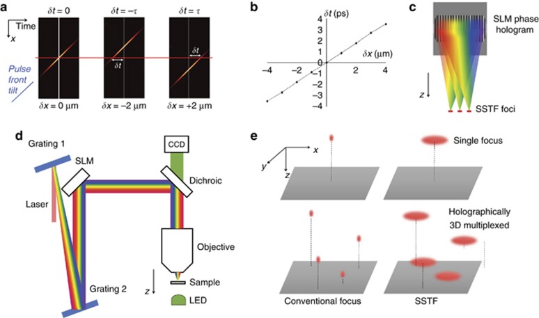
Figure 1
( a ) Effect of a linear phase gradient on the SSTF focus. Images show simulated results of spaceu2013time ( x , t ) intensity variations of temporal foci. Left to right: no phase gradient, linear pha...
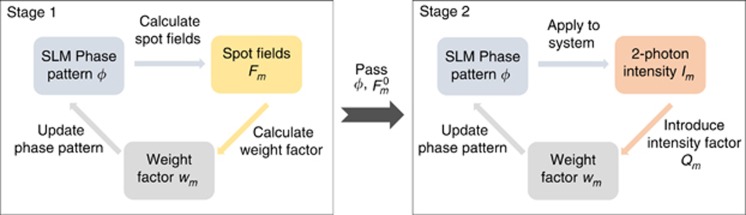
Figure 2
Flow chart illustrating the two-stage process for updating the phase pattern in the hologram design.
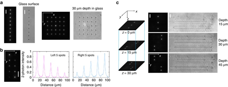
Figure 3
( a ) The images of two-photon emission and fabrication in glass for a 2D 1 u00d7 9 array and a 2D 5 u00d7 5 SSTF multiple focal array. The images from left to right: two-photon image of 1 u00d7 9 arr...
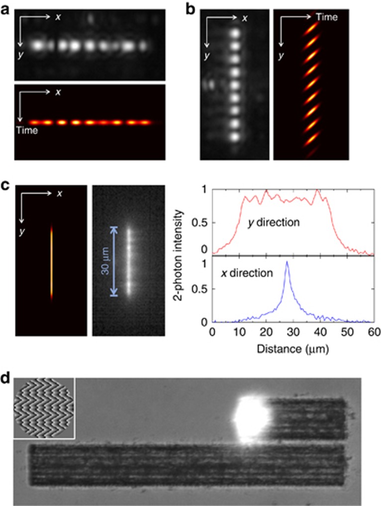
Figure 4
( a ) Top: Image of nine spatiotemporal spots in an array orthogonal to the direction of spatial chirp ( x axis). Bottom: simulation of intensity profile in the time domain ( x -time profile). The dis...
Figure images are served from the NIH/NLM PubMed Central Open Access Subset or Europe PMC; copyright remains with the publishers and authors.
💬 Discussion
0 commentsNo comments yet. Be the first to start a discussion!
Leave a Comment