Abstract
Due to their ability to serve as fluorophores and drug delivery vehicles, quantum dots are a powerful tool for theranostics-based clinical applications. In this study, microneedle devices for transdermal drug delivery were fabricated by means of two-photon polymerization of an acrylate-based polymer. We examined proliferation of cells on this polymer using neonatal human epidermal keratinocytes and human dermal fibroblasts. The microneedle device was used to inject quantum dots into porcine skin; imaging of the quantum dots was performed using multiphoton microscopy.
🔬 Techniques
🔬 Cell Lines
🏭 Microscope Brands
🧪 Reagent Suppliers
🔴 Lasers
💻 Software Details
🏛️ Research Organizations (ROR)
Affiliated research institutions:
📋 Methods
An ultraviolet light-sensitive acrylate-based polymer, e-shell 300 (EnvisionTEC, Gladbeck, Germany), was examined in this study. This rigid, tough, perspiration-resistant material is processed using single-photon polymerization for use in a variety of medical applications, including hearing aid shells and other Class IIa medical devices. Class IIa medical devices include non-invasive active medical devices for channeling and/or storing liquids for administration to the human body. 47 Information provided by the supplier indicates that e-shell is comprised of 10-25 % wt urethane dimethacrylate (CAS 72869-86-4) and 10-20% tetrahydrofurfuryl-2-methacrylate (CAS 2455-24-5). The two photon polymerization process was used to produce several types of microneedle structures from the acrylate-based polymer. Femtosecond pulses (60 fs, λ=780 nm) from a Chameleon titanium:sapphire laser (Coherent, Santa Clara, CA) were used to polymerize the liquid acrylate-based polymer resin. The resin was polymerized along the trace of the laser focus, which was moved in three dimensions. A hurrySCAN® galvano scan head (Scanlabs, Puchheim, Germany) was used to control laser writing in lateral (X- and Y-) dimensions. Movement in the height (Z-) dimension and movement from one structure to another structure were achieved using three C-843 linear translation stages (Physik Instrumente, Karlsruhe, Germany). Fabrication of the microneedle structures was guided by input stererolithography (STL) files, which were prepared using Solidworks Education Edition 2009 commercial software (Dassault Systemes SA, Velizy, France). The unpolymerized acrylate-based polymer resin was placed in between two glass cover slips; the resin was enclosed using a 1 mm thick polydimethylsiloxane ring. The structures were washed using isopropanol in order to remove the unirradiated resin. The structures were subsequently exposed to an ELC-410 ultraviolet curing lamp (Electro-Lite, Bethel, CT). Solid microneedles were initially fabricated using several processing parameters in order to obtain appropriate conditions for subsequent fabrication of hollow microneedles. Above an upper threshold of laser intensity, burning of the resin will occur. Below a lower threshold of laser intensity, polymerization of the resin will not occur. Processing parameters also alter voxel height and voxel width; these parameters affect shape and integrity of two photon polymerization-fabricated structures. An array of solid microneedles was initially fabricated using two photon polymerization; structures were fabricated with an input file height of 750 μm and base diameter of 125 μm. The objective, laser energy, laser wavelength, layer spacing, raster spacing, and mark speed were maintained at 10×, 320 mW, 780 nm, 10 μm, 1.5 μm, and 50-250 (arbitrary units) respectively. Hollow microneedles were subsequently fabricated on glass cover slips by means of two photon polymerization. One set of microneedles was produced using an input file height of 375 μm, base diameter of 250 μm, and channel diameter of 30 μm. Another set of microneedles was produced using an input file height of 500 μm, base diameter of 250 μm, and channel diameter of 30 μm. The objective, laser energy, laser wavelength, layer spacing, raster spacing, and mark speed were maintained at 10×, 320 mW, 780 nm, 10 μm, 1.5 μm, and 100 respectively. Freestanding microneedle arrays, containing both the substrate and the microneedles, were then fabricated using two photon polymerization. The 5× objective was used instead of the 10× objective due to limitations associated with radial laser intensity degradation in the focal plane. Changing the objective resulted in a reduction in two photon processing resolution; however, changing the objective was necessary in order to fabricate the large freestanding microneedle array structure. Freestanding microneedle arrays were fabricated in three steps due to radial laser intensity degradation. The border was initially fabricated; this structure enables handling of the freestanding microneedle array without damage to the microneedles. The objective, laser energy, laser wavelength, layer spacing, raster spacing, and mark speed were maintained at 5×, 570 mW, 780 nm, 25 μm, 2 μm, and 40 respectively. The substrate was then fabricated; it exhibited a three-by-three array structure with 500 μm spacing. The objective, laser energy, laser wavelength, layer spacing, raster spacing, and mark speed were maintained at 5×, 370 mW, 780 nm, 25 μm, 1.4 μm, and 60 respectively. A 100 μm overlap between the border and the substrate was used to ensure good bonding between structures. An array of microneedles was subsequently fabricated on the substrate. A computer-aided design drawing of the microneedle structure is shown in Figure 2a . Microneedles was produced with a conical opening at the base; structures were fabricated with an input file cylindrical base height of 250 μm, cylindrical base diameter of 400 μm, needle height of 608 μm, needle base diameter of 200 μm, and channel diameter of 110 μm. The objective, laser energy, laser wavelength, layer spacing, raster spacing, and mark speed were maintained at 5×, 370 mW, 780 nm, 25 μm, 1.4 μm, and 60 respectively. A 60 μm overlap between the substrate and the microneedles was used to ensure a strong bonding between structures. The structures were subsequently exposed to an ultraviolet curing lamp. The structures were subsequently removed from the glass cover slips. The structures were washed using isopropanol in order to remove the unirradiated resin. Details on fabrication of freestanding microneedle arrays are provided in Figure 2b . To confirm the unobstructed nature of the channels, 200 mbar vacuum suction was applied; isopropanol was placed on the array and pulled through the microneedles. Scanning electron microscopy imaging of the microneedle arrays was performed using an S-3200 variable pressure instrument (Hitachi, Tokyo, Japan) with a Robinson™ backscattered electron detector. Energy dispersive x-ray spectroscopy was used to obtain the elemental composition of the acrylate-based polymer microneedle arrays.
Show full methods section
An ultraviolet light-sensitive acrylate-based polymer, e-shell 300 (EnvisionTEC, Gladbeck, Germany), was examined in this study. This rigid, tough, perspiration-resistant material is processed using single-photon polymerization for use in a variety of medical applications, including hearing aid shells and other Class IIa medical devices. Class IIa medical devices include non-invasive active medical devices for channeling and/or storing liquids for administration to the human body. 47 Information provided by the supplier indicates that e-shell is comprised of 10-25 % wt urethane dimethacrylate (CAS 72869-86-4) and 10-20% tetrahydrofurfuryl-2-methacrylate (CAS 2455-24-5). The two photon polymerization process was used to produce several types of microneedle structures from the acrylate-based polymer. Femtosecond pulses (60 fs, λ=780 nm) from a Chameleon titanium:sapphire laser (Coherent, Santa Clara, CA) were used to polymerize the liquid acrylate-based polymer resin. The resin was polymerized along the trace of the laser focus, which was moved in three dimensions. A hurrySCAN® galvano scan head (Scanlabs, Puchheim, Germany) was used to control laser writing in lateral (X- and Y-) dimensions. Movement in the height (Z-) dimension and movement from one structure to another structure were achieved using three C-843 linear translation stages (Physik Instrumente, Karlsruhe, Germany). Fabrication of the microneedle structures was guided by input stererolithography (STL) files, which were prepared using Solidworks Education Edition 2009 commercial software (Dassault Systemes SA, Velizy, France). The unpolymerized acrylate-based polymer resin was placed in between two glass cover slips; the resin was enclosed using a 1 mm thick polydimethylsiloxane ring. The structures were washed using isopropanol in order to remove the unirradiated resin. The structures were subsequently exposed to an ELC-410 ultraviolet curing lamp (Electro-Lite, Bethel, CT). Solid microneedles were initially fabricated using several processing parameters in order to obtain appropriate conditions for subsequent fabrication of hollow microneedles. Above an upper threshold of laser intensity, burning of the resin will occur. Below a lower threshold of laser intensity, polymerization of the resin will not occur. Processing parameters also alter voxel height and voxel width; these parameters affect shape and integrity of two photon polymerization-fabricated structures. An array of solid microneedles was initially fabricated using two photon polymerization; structures were fabricated with an input file height of 750 μm and base diameter of 125 μm. The objective, laser energy, laser wavelength, layer spacing, raster spacing, and mark speed were maintained at 10×, 320 mW, 780 nm, 10 μm, 1.5 μm, and 50-250 (arbitrary units) respectively. Hollow microneedles were subsequently fabricated on glass cover slips by means of two photon polymerization. One set of microneedles was produced using an input file height of 375 μm, base diameter of 250 μm, and channel diameter of 30 μm. Another set of microneedles was produced using an input file height of 500 μm, base diameter of 250 μm, and channel diameter of 30 μm. The objective, laser energy, laser wavelength, layer spacing, raster spacing, and mark speed were maintained at 10×, 320 mW, 780 nm, 10 μm, 1.5 μm, and 100 respectively. Freestanding microneedle arrays, containing both the substrate and the microneedles, were then fabricated using two photon polymerization. The 5× objective was used instead of the 10× objective due to limitations associated with radial laser intensity degradation in the focal plane. Changing the objective resulted in a reduction in two photon processing resolution; however, changing the objective was necessary in order to fabricate the large freestanding microneedle array structure. Freestanding microneedle arrays were fabricated in three steps due to radial laser intensity degradation. The border was initially fabricated; this structure enables handling of the freestanding microneedle array without damage to the microneedles. The objective, laser energy, laser wavelength, layer spacing, raster spacing, and mark speed were maintained at 5×, 570 mW, 780 nm, 25 μm, 2 μm, and 40 respectively. The substrate was then fabricated; it exhibited a three-by-three array structure with 500 μm spacing. The objective, laser energy, laser wavelength, layer spacing, raster spacing, and mark speed were maintained at 5×, 370 mW, 780 nm, 25 μm, 1.4 μm, and 60 respectively. A 100 μm overlap between the border and the substrate was used to ensure good bonding between structures. An array of microneedles was subsequently fabricated on the substrate. A computer-aided design drawing of the microneedle structure is shown in Figure 2a . Microneedles was produced with a conical opening at the base; structures were fabricated with an input file cylindrical base height of 250 μm, cylindrical base diameter of 400 μm, needle height of 608 μm, needle base diameter of 200 μm, and channel diameter of 110 μm. The objective, laser energy, laser wavelength, layer spacing, raster spacing, and mark speed were maintained at 5×, 370 mW, 780 nm, 25 μm, 1.4 μm, and 60 respectively. A 60 μm overlap between the substrate and the microneedles was used to ensure a strong bonding between structures. The structures were subsequently exposed to an ultraviolet curing lamp. The structures were subsequently removed from the glass cover slips. The structures were washed using isopropanol in order to remove the unirradiated resin. Details on fabrication of freestanding microneedle arrays are provided in Figure 2b . To confirm the unobstructed nature of the channels, 200 mbar vacuum suction was applied; isopropanol was placed on the array and pulled through the microneedles. Scanning electron microscopy imaging of the microneedle arrays was performed using an S-3200 variable pressure instrument (Hitachi, Tokyo, Japan) with a Robinson™ backscattered electron detector. Energy dispersive x-ray spectroscopy was used to obtain the elemental composition of the acrylate-based polymer microneedle arrays.
Fourier transform infrared spectroscopy
(FTIR) was performed using a Nexus 470 system with a continuum microscope and an OMNI sampler (Thermo Fisher, Waltham, MA); spectral analysis was performed with OMNIC™ software (Thermo Fisher, Waltham, MA). Material for Fourier transform infrared spectroscopy was prepared by sandwiching resin between two glass cover slips with a polydimethylsiloxane spacer (thickness=1 mm, diameter= 5 mm);the resin was polymerized using an ELC-410 ultraviolet curing lamp. Elastic modulus (relative stiffness of a material against elastic deformation) and hardness (resistance of a material to penetration and/or plastic deformation) are critical parameters for materials used in fabrication of microneedle devices. Material for nanoindentation testing was prepared by sandwiching resin between two glass cover slips with a polydimethylsiloxane spacer (thickness=1 mm, diameter= 5 mm);the resin was polymerized using an ELC-410 ultraviolet curing lamp. An Ultra Nano Hardness Tester (CSM Instruments, Needham, MA) containing an indenter tip with Berkovitch geometry was used to obtain elastic modulus and hardness data for the acrylate-based polymer. Ten indentations were performed; the indenter tip was driven into the surface of the material with up to 2 mN normal load, 4 mN/min loading rate, and 4 mN/min unloading rate. Partial or complete relaxation was achieved by reducing the load after the maximum load had been achieved. Indentation hardness and elastic modulus were obtained from the load-displacement data using the Oliver and Pharr method. 48 Proliferation of cells on the acrylate-based polymer was assessed by the MTT (3-(4,5-dimethylthiazol-2-yl)2,5-diphenyl tetrazolium bromide) assay; this assay is based on reduction of a yellow tetrazolium salt (MTT) to a purple formazan dye by the succinic dehydrogenase enzyme within mitochondria. 49 Glass cover slips (diameter=12.5 mm) (n=4), empty wells within γ-irradiated sterile polystyrene plates (n=4) (Sigma-Aldrich, St. Louis, MO), and e-shell 300 acrylate-based polymer wafers (n=4) were evaluated. Cylindrical wafers (thickness=1.5 mm, diameter=14.0 mm) of the acrylate-based polymer were prepared using a Perfactory® Standard SXGA+ UV (EnvisionTEC, Gladbeck, Germany) stereolithography system. This system uses stereolithography (STL) files to guide an ultraviolet light beam over the acrylate-based polymer resin. Illumination in the X- and Y- dimensions was regulated by directed light projection (DLP) optics (Texas Instruments, Dallas, TX); the chip used for wafer fabrication exhibits 1280 × 1024-pixel resolution. Acrylate-based polymer samples were subsequently washed in isopropanol and post-cured using the ELC-410 UV curing lamp. The acrylate-based polymer wafers and glass cover slips were rinsed twice in 70% ethanol for thirty minutes and then exposed to ultraviolet B light for two hours. The acrylate-based polymer wafers and glass cover slips were subsequently rinsed twice in Hanks' Balanced Salt Solution (HBSS) and once in culture medium. The acrylate-based polymer wafers and glass cover slips were then placed in 2 mL of medium and stored in an incubator until seeding.
Cryopreserved neonatal human epidermal keratinocytes
(HEK) and human dermal fibroblasts (HDF) were purchased from a commercial source (Lonza, Walkersville, MD). Cells were propagated in 75cm 2 flasks, grown to 75% confluency, harvested, and seeded (40,000 cells per well) on acrylate-based polymer wafers, on glass cover slips, and in polystyrene well plates. Culturing was performed with keratinocyte growth media (KGM-2) (Lonza, Walkersville, MD) and fibroblast growth media (FGM-2) (Lonza, Walkersville, MD). The acrylate-based polymer wafers were compared to both empty polystyrene well plates and glass cover slips. Since aspiration of solutions was associated with detachment of cells from the test materials, all media changes and material rinsing were accomplished by moving the test materials from one solution to the other with forceps. Aspiration was performed for evaluation of cell proliferation within the empty wells. Test materials were placed in fresh medium after forty-eight hours, which correlated with 80% confluency of both neonatal human epidermal keratinocytes and human dermal fibroblasts; cell proliferation on test materials was assessed twenty-four hours later. The test materials were rinsed with Hanks' Balanced Salt Solution, desorbed with isopropyl alcohol, and agitated. 100μl of isopropyl alcohol was transferred to a new twenty-four well plate; absorbance was spectrophotometrically evaluated (λ=550 nm) using a Multiskan RC plate reader (Labsystems Inc, Franklin, MA). Since human skin is similar to porcine skin, an ex vivo porcine skin model was used to evaluate quantum dot delivery. 50 Full thickness skin was obtained from euthanized female weanling Yorkshire pigs. The back area of the pig was clipped; two days later, full thickness skin was surgically removed. The skin was refrigerated until the quantum dot injection, which occurred one day after surgical removal. Animal care and experimental use were performed according to approved guidelines by the local Animal Care and Use Committee (North Carolina State University, Raleigh, NC). A LSM-710 multiphoton microscope (Carl Zeiss AG, Oberkochen, Germany) was used for imaging delivery of quantum dots into porcine skin. Qdot® 565 ITK™ carboxyl quantum dots (amount=250 μL, concentration=8 μM, pH=9.0) were obtained from a commercial source (Invitrogen, Carlsbad, CA). Information provided by the supplier indicates that the quantum dots contained a CdSe core and a crystalline ZnS shell; an amphophilic carboxyl coating enables dispersion of quantum dots in aqueous solutions and may serve to minimize generation of free cadmium. The freestanding microneedle array was initially pressed into the skin. A piece of polydimethylsiloxane containing a hole that was larger than the microneedle array but smaller than the substrate was placed on the backside of the microneedle array in order to obtain a seal. A syringe was filled with the quantum dot solution. A piece of polydimethylsiloxane with a Luer-lock fitting was attached in order to completely seal the connection between the array and the syringe. 250 μL of 8 μM quantum dot solution was diluted in deionized water to a total volume of 1 mL prior to injection; 250 μl of this diluted solution was injected via the microneedle array prior to imaging. The microneedle array was kept in the skin during imaging. Quantum dot solution was topically applied to the surface of a separate porcine skin for comparison purposes. The microneedles and the quantum dots were simultaneously imaged since multiphoton excitation occurs for both the e-shell 300 acrylate based polymer and the Qdot® 565 ITK™ carboxyl quantum dots at λ=800 nm. Multiphoton microscopy was performed with a femtosecond laser (λ=800 nm) (Chameleon, Coherent, Santa Clara, CA); a pixel dwell time of 1.58 μs were used for imaging. A 20× plan-apochromat water immersion objective was utilized in this study; a droplet of water was placed on the backside of the microneedle array. Water was the only medium between the objective and the sample. Z-stack images were obtained of (a) a porcine skin section containing topically applied quantum dot solution, (b) a porcine skin section containing a freestanding microneedle array without injection of quantum dots, and (c) a porcine skin section containing a freestanding microneedle array immediately after quantum dot injection; image acquisition was completed less than fifteen minutes after quantum dot injection. Imaris 7.0 image analysis software (Bitplane AG, Zurich, Switzerland) was used to produce surface rendering images of the microneedles and maximum projection images of the quantum dots from the z-stack data; these images provide enhanced visualization of quantum dot delivery.
📊 Figures

Figure 1
a) Schematic of the two photon polymerization system. Femtosecond laser pulses pass through a beam expander and a filter wheel before being focused on the objective. Scanning mirrors control the locat...

Figure 2
a) Input computer-aided design drawing of hollow microneedles processed via two photon polymerization. b) Diagram of hollow microneedle device fabrication by means of two photon polymerization.

Figure 3
Fourier transform infrared spectrum of e-shell 300 acrylate-based polymer.

Figure 4
MTT viability of neonatal human epidermal keratinocytes and human dermal fibroblasts on e-shell 300 acrylate-based polymer, polystyrene well plate, and glass is shown. Error bars indicate standard err...

Figure 5
Scanning electron microscopy image obtained at 45u00b0 tilt of solid e-shell 300 microneedles, which were created by means of two photon polymerization. Mark speeds (from front to back) of 250, 50, 10...
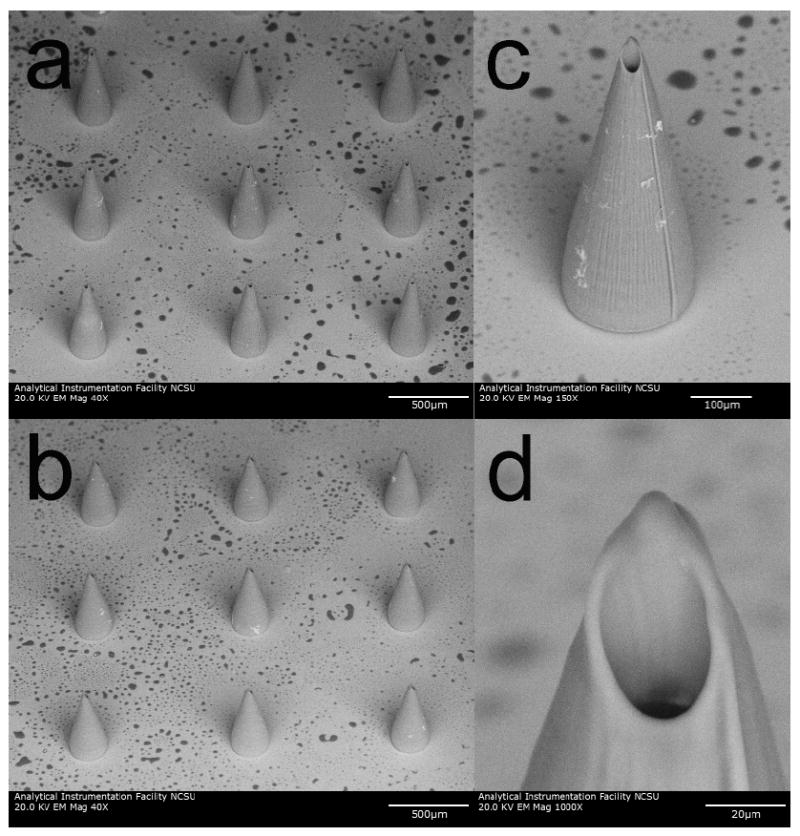
Figure 6
Scanning electron microscopy images obtained at 45u00b0 tilt of e-shell 300 hollow microneedles on glass substrates, which were produced using two photon polymerization. a) Image of 614 +/- 12 u03bcm ...

Figure 7
Scanning electron microscopy images of e-shell 300 hollow microneedle array, which was produced using two photon polymerization. a) Image of microneedle array obtained at 45u00b0 tilt. b) Image of ind...
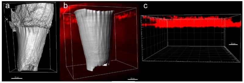
Figure 8
Multiphoton microscopy images of quantum dot injection via two photon polymerization-fabricated e-shell 300 microneedle array as well as via topical application. The microneedles are presented as surf...
Figure images are served from the NIH/NLM PubMed Central Open Access Subset or Europe PMC; copyright remains with the publishers and authors.
💬 Discussion
0 commentsNo comments yet. Be the first to start a discussion!
Leave a Comment