Abstract
AbstractSelective-plane illumination microscopy has proven to be a powerful imaging technique due to its unsurpassed acquisition speed and gentle optical sectioning. However, even in the case of multiview imaging techniques that illuminate and image the sample from multiple directions, light scattering inside tissues often severely impairs image contrast. Here we combine multiview light-sheet imaging with electronic confocal slit detection implemented on modern camera sensors. In addition to improved imaging quality, the electronic confocal slit detection doubles the acquisition speed in multiview setups with two opposing illumination directions allowing simultaneous dual-sided illumination. Confocal multiview light-sheet microscopy eliminates the need for specimen-specific data fusion algorithms, streamlines image post-processing, easing data handling and storage.
🔬 Techniques
🔭 Microscopes
🧬 Organisms
✨ Fluorophores
🧪 Sample Preparation
🏭 Microscope Brands
🧪 Reagent Suppliers
📷 Detectors
💻 Software Details
🏛️ Research Organizations (ROR)
Affiliated research institutions:
📋 Methods
Light-sheet microscope setup
Here we briefly summarize the key components of our confocal MuVi-SPIM setup. The microscope consists of two opposing illumination and two opposing detection arms. All experiments had the following objective configuration: two Nikon 10X numerical aperture 0.3 water-dipping objective for illumination and two Nikon 25X numerical aperture 1.1 water-dipping objective lenses for detection 11 . The main modifications compared to the MuVi-SPIM setup are a 50:50 laser beam splitter (non-polarized) to direct the laser light to both illumination objectives, tube lenses (Nikon 200 and 300 mm) to yield an effective magnification of 25X or 37.5X depending on the size of the sample. Additionally, the sample fluorescence was imaged onto two custom modified Hamamatsu Flash 4 V1 cameras enabling confocal slit detection. These cameras are now commercially available as Hamamatsu Flash 4 V2, which include a ‘light sheet mode' based on our collaboration. A custom written script ( Supplementary Software and Supplementary Note 3 ) calculates necessary parameters for the slit calibration. For all sample imaging we used a theoretical beam-slit size based on the 1/e 2 size of the illumination beam. Hardware control Electronic confocal slit detection requires precise timing and position control of cameras, lasers and galvanometric mirrors to ensure alignment of the illumination beam with the active area of the camera. As outlined above, we estimated the timing precision to be in the range of a few microseconds. For our optical setup, a galvanometric mirror amplitude of 1 V is sufficient to scan across the entire field of view of the camera (532 μm). A minimal slit size of 4 pixels thus yields a required precision in galvanometric mirror control voltage of 1 V*4/2048=2 mV. This can be achieved with 16-bit precision DAC. We used a custom written LabView (National Instruments) control software for synchronization of timings across all microscope devices. All trigger and analogue voltage traces are calculated by a field programmable gate array (FPGA, National Instrument NI PCIe-7842 R with a Virtex-5 FPGA) that ensures precise timing in the sub-μs range (40-MHz clock frequency). Following our collaboration with Hamamatsu Photonics, Japan, electronic confocal slit detection, also called ‘light-sheet mode', has been made available with version 2 (V2) release of the Hamamatsu Flash 4 camera. Other camera manufacturers have recently released cameras with similar features (Andor Technology, UK and PCO Imaging, Germany).
Show full methods section
Light-sheet microscope setup
Here we briefly summarize the key components of our confocal MuVi-SPIM setup. The microscope consists of two opposing illumination and two opposing detection arms. All experiments had the following objective configuration: two Nikon 10X numerical aperture 0.3 water-dipping objective for illumination and two Nikon 25X numerical aperture 1.1 water-dipping objective lenses for detection 11 . The main modifications compared to the MuVi-SPIM setup are a 50:50 laser beam splitter (non-polarized) to direct the laser light to both illumination objectives, tube lenses (Nikon 200 and 300 mm) to yield an effective magnification of 25X or 37.5X depending on the size of the sample. Additionally, the sample fluorescence was imaged onto two custom modified Hamamatsu Flash 4 V1 cameras enabling confocal slit detection. These cameras are now commercially available as Hamamatsu Flash 4 V2, which include a ‘light sheet mode' based on our collaboration. A custom written script ( Supplementary Software and Supplementary Note 3 ) calculates necessary parameters for the slit calibration. For all sample imaging we used a theoretical beam-slit size based on the 1/e 2 size of the illumination beam. Hardware control Electronic confocal slit detection requires precise timing and position control of cameras, lasers and galvanometric mirrors to ensure alignment of the illumination beam with the active area of the camera. As outlined above, we estimated the timing precision to be in the range of a few microseconds. For our optical setup, a galvanometric mirror amplitude of 1 V is sufficient to scan across the entire field of view of the camera (532 μm). A minimal slit size of 4 pixels thus yields a required precision in galvanometric mirror control voltage of 1 V*4/2048=2 mV. This can be achieved with 16-bit precision DAC. We used a custom written LabView (National Instruments) control software for synchronization of timings across all microscope devices. All trigger and analogue voltage traces are calculated by a field programmable gate array (FPGA, National Instrument NI PCIe-7842 R with a Virtex-5 FPGA) that ensures precise timing in the sub-μs range (40-MHz clock frequency). Following our collaboration with Hamamatsu Photonics, Japan, electronic confocal slit detection, also called ‘light-sheet mode', has been made available with version 2 (V2) release of the Hamamatsu Flash 4 camera. Other camera manufacturers have recently released cameras with similar features (Andor Technology, UK and PCO Imaging, Germany).
Deconvolution
Multiview fusion deconvolution was performed with the Fiji Multiview Reconstruction plugin, (Fiji version 1.50b). For Supplementary Fig. 8 , deconvolution was done with Huygens Pro with an under development SPIM module, Scientific Volume Imaging B.V, version 15.05.1p1 64b. All calculations were performed with the theoretical PSF of the optical setup. Zebrafish Embryos were collected after fertilization and incubated at 28 °C. The temperature during imaging was kept constant at 23 °C. Embryos were mounted in an agarose gel (Sigma-Aldrich) inside a glass micropipette (Brand 100 μl) and a short cylinder of agarose containing the sample was then pushed out and placed in the microscope.
Drosophila embryo preparation and mounting
Embryos were collected on apple juice agar plates and then dechorionated for 1 min in a fresh 50% bleach solution. Embryos were mounted in a gelrite gel (Sigma-Aldrich) inside a shortened glass micropipette (Brand 100 μl). A short segment of the gel cylinder containing the sample was pushed out of the micropipette and the pipette inserted into the microscope. Mouse All animal works were performed in the animal facility at the European Molecular Biology Laboratory, according to the permission by the institutional veterinarian overseeing the operation (ARC number TH11 00 11). The animal facility is operating according to international animal welfare rules (Federation for Laboratory Animal Science Associations guidelines and recommendations). Mouse embryos were isolated 6.5 days after plug formation by natural matings between R26-H2B-mCherry 21 and mG (ref. 22 ). Embryos were dissected from the uterus and cultured in phenol red-free Dulbecco's modified Eagle's medium (Gibco, 11880-028) supplemented with 10% fetal bovine serum (PAA laboratories, A15-080), in 5% CO2 atmosphere at 37 °C and within 2 h imaged after mounting them in ultra-low melt agarose (StarLab GmbH, Germany) inside a glass micropipette similarly to zebrafish embryos. Ascidians Adult Phallusia mammillata were acquired from the Roscoff Marine Biological Station (France). Embryo handling was done as described in Sardet et al. 23 . The membranes were marked with FM464 (6 μM). The embryo was imaged in artificial seawater at a temperature of 18C and mounted in the well of a 0.8% GelRite (SIGMA, G1910) plug.
Supplementary Material Supplementary Information Supplementary Figures 1-8, Supplementary Notes 1-3 and Supplementary References Supplementary Movie 1 Illustration of light scattering by parked beam analysis. Animation of the beam scanning through a Drosophila embryo (stage 14, anterior pole up, 60 μm from the surface) from acquired parked beam images. The red rectangle depicts shape of confocal slit used as a mask to create synthetic images. The beam data is used to illustrate the successive buildup of the widefield, confocal, and rejected light images as the beam scans over the field of view. Scale bar 50 μm. Supplementary Movie 2 Confocal and rejected image as a function of slit size. The confocal and rejected images were calculated from the parked beam data presented in Supplementary Movie 1 with increasing slit sizes. For slit sizes below the beam-slit size of 40pixels, most of the scattered light is rejected by the confocal detection. For larger slit sizes the wide field image is approached. Scale bar 50 μm. Supplementary Movie 3 Demonstration of confocal detection on sCMOS sensor. Automatic acquisition of a single plane inside a Drosophila embryo with increasing slit size. Here the beam-slit size is 1.5 and the total exposure time is 51ms independent of the slit size. All images are scaled to the same maximum intensity to facilitate comparison of the dynamic range. Scale bar 50 μm. Supplementary Movie 4 Rendering of Drosophila embryo highlighting muscle structures. Comparison of widefield and confocal detection of a Drosophila embryo expressing a muscle marker (Kettin-mCherry, 14hrs AEL). Confocal detection reveals the fine structure of the sarcromeres. Scale bar 50 μm. Supplementary Movie 5 Comparison of widefield and confocal detection of a Zebrafish eye. The movie shows consecutive z-slices (1μm spacing) through the developing eye of a Zebrafish embryo (1dpf) expressing nuclear and membrane markers (injected mRNA of H2B-GFP and Lyn-tdTomato). Scale bar 50 μm. Supplementary Movie 6 Rendering of a mouse embryo. Comparison of widefield (left) and confocal (right) detection of a mouse embryo (6.5 days post fertilization) highlighting nuclei (H2B-mCherry) and cell membranes (mG-EGFP). Sigmoidal fusion was used to combine the widefield images from the opposing camera views, while the confocal images were directly fused. The 3D dataset was cut open at the middle of the embryo to visualize the inner morphology. Scale bar 50 μm. Supplementary Software Supplementary Software for eCSD calibration. Parked beam images are used as input for calculation of three camera parameters necessary for confocal slit synchronization with scanning illumination beam. Example input images are provided.
📊 Figures
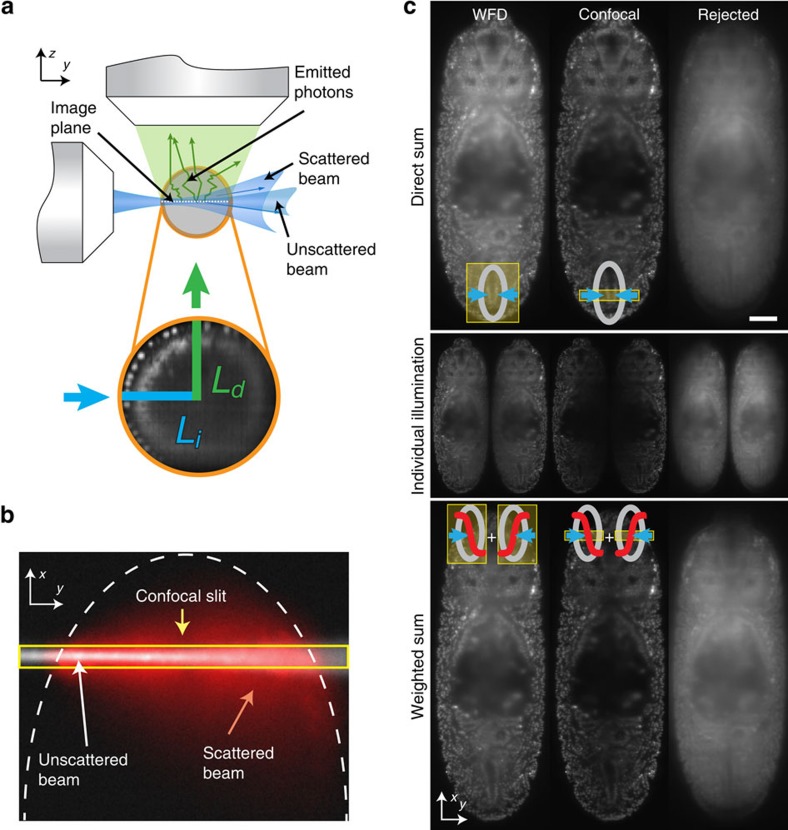
Figure 1
Confocal slit detection enables simultaneous dual-sided illumination with improved image quality.
( a ) Illumination (blue) and detection (green) photons in light-sheet microscopy are both independently subject to light scattering in biological specimens that lead to imaging artifacts. Image quali...

Figure 2
Scattered light reduction and data fusion with electronic confocal slit detection.
( a ) Left- and right-sided illuminations of a single (sagittal) plane 50u2009u03bcm inside the Drosophila embryo expressing His2Av-RFP1 is shown for widefield and eCSD detection. The decrease in imag...
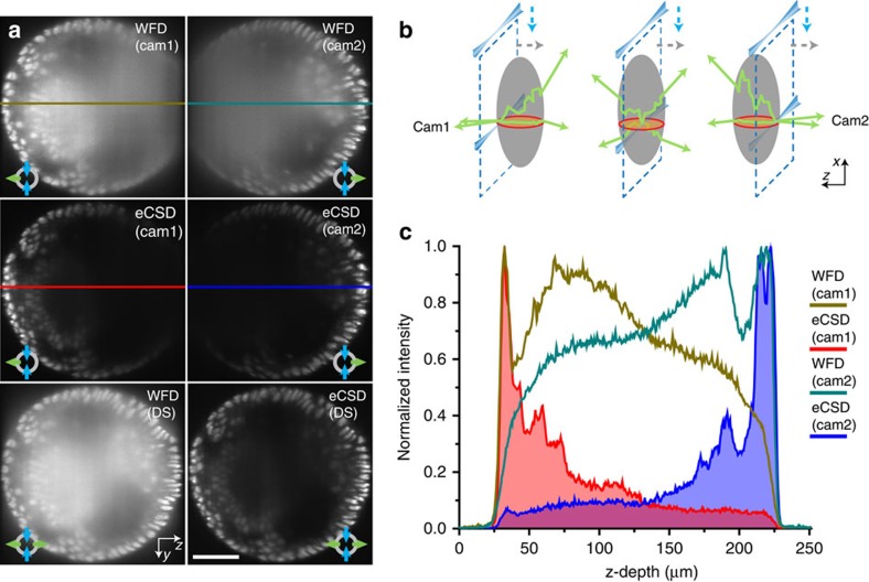
Figure 3
Confocal slit detection enables direct fusion of opposing views.
( a ) Transverse planes of 3D data stacks halfway between the anterior and posterior pole of an embryo expressing His2Av-mCherry (see red circle in ( b )) are shown for widefield and eCSD detection. T...
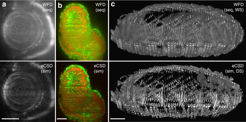
Figure 4
eCSD multiview light-sheet images with direct data fusion.
( a u2013 c ) Examples of contrast enhancement with sequential or simultaneous illumination, direct or weighted sum by confocal versus widefield detection for different organisms and biological marker...
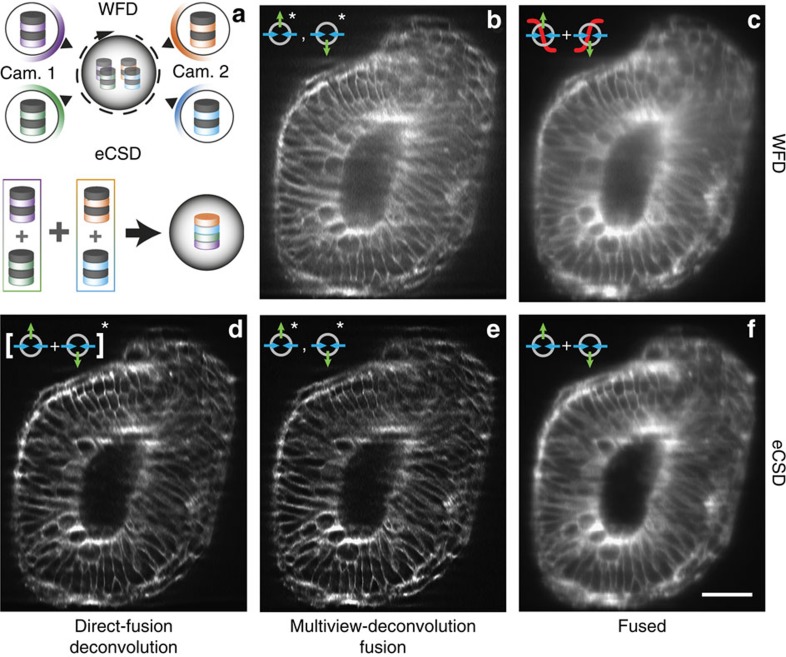
Figure 5
Comparison of multiview-deconvolution fusion and eCSD facilitated direct fusion.
( a ) Illustration of multiview-deconvolution fusion pipeline (top) and optimized direct-fusion deconvolution data processing for eCSD data sets. In multiview-deconvolution fusion all views (in our ca...
Figure images are served from the NIH/NLM PubMed Central Open Access Subset or Europe PMC; copyright remains with the publishers and authors.
💬 Discussion
0 commentsNo comments yet. Be the first to start a discussion!
Leave a Comment