Abstract
AbstractMultimodal non-linear microscopy combining coherent anti-Stokes Raman scattering, second harmonic generation, and two-photon excited fluorescence has proved to be a versatile and powerful tool enabling the label-free investigation of tissue structure, molecular composition, and correlation with function and disease status. For a routine medical application, the implementation of this approach into an in vivo imaging endoscope is required. However, this is a difficult task due to the requirements of a multicolour ultrashort laser delivery from a compact and robust laser source through a fiber with low losses and temporal synchronization, the efficient signal collection in epi-direction, the need for small-diameter but highly corrected endomicroobjectives of high numerical aperture and compact scanners. Here, we introduce an ultra-compact fiber-scanning endoscope platform for multimodal non-linear endomicroscopy in combination with a compact four-wave mixing based fiber laser. The heart of this fiber-scanning endoscope is an in-house custom-designed, single mode, double clad, double core pure silica fiber in combination with a 2.4 mm diameter NIR-dual-waveband corrected endomicroscopic objective of 0.55 numerical aperture and 180 µm field of view for non-linear imaging, allowing a background free, low-loss, high peak power laser delivery, and an efficient signal collection in backward direction. A linear diffractive optical grating overlays pump and Stokes laser foci across the full field of view, such that diffraction-limited performance is demonstrated for tissue imaging at one frame per second with sub-micron spatial resolution and at a high transmission of 65% from the laser to the specimen using a distal resonant fiber scanner.
🔬 Techniques
🔭 Microscopes
🧬 Organisms
🧪 Sample Preparation
🔬 Cell Lines
🏭 Microscope Brands
📷 Detectors
🔎 Objectives
🎨 Filters
🏛️ Research Organizations (ROR)
Affiliated research institutions:
📋 Methods
Experimental Set-up The experimental set-up for multimodal non-linear endomicroscopy consists of a compact all-fiber laser for CARS microscopy (CARS-1032, AFS, Germany) of a pulse duration of 20/60 ps, an average power of 20/100 mW at 795/1030 nm and a repetition rate of 1 MHz. The laser delivers synchronized pump and Stokes pulses in a PCF fiber connected to the custom coupling unit by a standard FC/PC connector. The laser beam is collimated by an achromatic lens ( f = 3 mm, #84–127, Edmund Optics, USA). In the collimated beam path, a 750 nm long-pass filter F1 (FELH0750, Thorlabs, USA) filters FWM from the fiber. The Stokes laser power is adjusted by a short-pass dichroic mirror (#86–696, Edmund Optics, USA), and a dichroic mirror (SEM-FF757-Di01–25×36, Semrock, USA) is used to reflect CARS/SHG and TPEF signals. The signals are filtered by bandpass filters and focused onto the PMT detector (H10723-20MOD, Hamamatsu, Japan) by an achromatic lens. The individual filters are summarized in Table 2 . Table 2 list of bandbass filters for selection of the non-linear signals, all filters are from Semrock, USA Signal Bandpass filter CARS FF02-675/67-25 TPEF1 FF01-578/105-25 TPEF2 FF01-458/64-25 SHG FF01-514/3-25 The fibers and the connecting wires are protected by a medical endoscopic tube, and the endoscopic head is sealed to enable the clinical application. The whole length of the DCDC fiber from the endoscope head to the coupling unit is about 1 m. The endoscopic head consists of the fiber scanner and the endomicroscopic objective, which are mounted in a stainless steel tube with an outer diameter of 2.4 mm and a length of 38.94 mm. The scanning procedure is realized using resonant piezo scanning techniques 14 , 18 , 19 . Blazed gratings The linear blazed gratings which are used to couple both laser wavelengths in the separated cores of the double-core double-clad fiber in the coupling unit and, also, to overlap the collimated, but slightly deflected beams again in the probe head were fabricated by a grey tone lithography on thin glass wafers (Fraunhofer IOF, Germany). The required grating periods g could be derived from the diffraction law in combination with the applied focal lengths f of the collimating lenses between the fiber and the grating, documentclass[12pt]{minimal} usepackage{amsmath} usepackage{wasysym} usepackage{amsfonts} usepackage{amssymb} usepackage{amsbsy} usepackage{mathrsfs} usepackage{upgreek} setlength{oddsidemargin}{-69pt} begin{document}$$g = frac{{fDelta lambda }}{a}$$end{document} g = f Δ λ a ∆λ is the wavelength difference between pump and Stokes wavelengths, and a corresponds to the distance between the centers of the two cores. With the wavelength difference of 235 nm, a core distance of 24 µm, and the respective focal lengths of the incoupling lens L3 of 4 mm and of the GRIN lens of 4.17 mm, the required grating periods were 39.4 and 40.8 µm. The design height of the blazed structure was chosen to provide optimum diffraction efficiency in the first order for a wavelength of 927 nm. The diffraction efficiencies were measured using collimated Gaussian beams of 0.5 mm diameter from single-mode fiber-coupled diode lasers at 1065, 780, 635, and 532 nm. The laser beams transmitted the gratings, and the optical power levels were measured for the different diffraction orders with a photodetector in reference to an area on the glass wafer without a diffractive structure. Diffraction efficiencies of more than 80% were measured in the first diffraction order for the wavelength of 780 and 1065 nm, and in the first two diffraction orders for 532 and 635 nm.
Show full methods section
Experimental Set-up The experimental set-up for multimodal non-linear endomicroscopy consists of a compact all-fiber laser for CARS microscopy (CARS-1032, AFS, Germany) of a pulse duration of 20/60 ps, an average power of 20/100 mW at 795/1030 nm and a repetition rate of 1 MHz. The laser delivers synchronized pump and Stokes pulses in a PCF fiber connected to the custom coupling unit by a standard FC/PC connector. The laser beam is collimated by an achromatic lens ( f = 3 mm, #84–127, Edmund Optics, USA). In the collimated beam path, a 750 nm long-pass filter F1 (FELH0750, Thorlabs, USA) filters FWM from the fiber. The Stokes laser power is adjusted by a short-pass dichroic mirror (#86–696, Edmund Optics, USA), and a dichroic mirror (SEM-FF757-Di01–25×36, Semrock, USA) is used to reflect CARS/SHG and TPEF signals. The signals are filtered by bandpass filters and focused onto the PMT detector (H10723-20MOD, Hamamatsu, Japan) by an achromatic lens. The individual filters are summarized in Table 2 . Table 2 list of bandbass filters for selection of the non-linear signals, all filters are from Semrock, USA Signal Bandpass filter CARS FF02-675/67-25 TPEF1 FF01-578/105-25 TPEF2 FF01-458/64-25 SHG FF01-514/3-25 The fibers and the connecting wires are protected by a medical endoscopic tube, and the endoscopic head is sealed to enable the clinical application. The whole length of the DCDC fiber from the endoscope head to the coupling unit is about 1 m. The endoscopic head consists of the fiber scanner and the endomicroscopic objective, which are mounted in a stainless steel tube with an outer diameter of 2.4 mm and a length of 38.94 mm. The scanning procedure is realized using resonant piezo scanning techniques 14 , 18 , 19 . Blazed gratings The linear blazed gratings which are used to couple both laser wavelengths in the separated cores of the double-core double-clad fiber in the coupling unit and, also, to overlap the collimated, but slightly deflected beams again in the probe head were fabricated by a grey tone lithography on thin glass wafers (Fraunhofer IOF, Germany). The required grating periods g could be derived from the diffraction law in combination with the applied focal lengths f of the collimating lenses between the fiber and the grating, documentclass[12pt]{minimal} usepackage{amsmath} usepackage{wasysym} usepackage{amsfonts} usepackage{amssymb} usepackage{amsbsy} usepackage{mathrsfs} usepackage{upgreek} setlength{oddsidemargin}{-69pt} begin{document}$$g = frac{{fDelta lambda }}{a}$$end{document} g = f Δ λ a ∆λ is the wavelength difference between pump and Stokes wavelengths, and a corresponds to the distance between the centers of the two cores. With the wavelength difference of 235 nm, a core distance of 24 µm, and the respective focal lengths of the incoupling lens L3 of 4 mm and of the GRIN lens of 4.17 mm, the required grating periods were 39.4 and 40.8 µm. The design height of the blazed structure was chosen to provide optimum diffraction efficiency in the first order for a wavelength of 927 nm. The diffraction efficiencies were measured using collimated Gaussian beams of 0.5 mm diameter from single-mode fiber-coupled diode lasers at 1065, 780, 635, and 532 nm. The laser beams transmitted the gratings, and the optical power levels were measured for the different diffraction orders with a photodetector in reference to an area on the glass wafer without a diffractive structure. Diffraction efficiencies of more than 80% were measured in the first diffraction order for the wavelength of 780 and 1065 nm, and in the first two diffraction orders for 532 and 635 nm.
Sample preparation
The polystyrene bead sample was prepared by depositing a high-density bead solution onto a standard cover glass. Biological sample measurements were performed using a fixed assembly. The probe head was placed on a microscope stage and held by a mechanical arm for precise positioning. The biological samples investigated in this study were prepared according to the regulations and disposed of properly after measurements. The Galleria mellonella larvae were embedded in distilled water for cryo-sectioning. Afterwards, the tissue sections were placed on the microscopy glass substrate.
Imaging parameters
Due to the 1 MHz repetition rate of the laser, the number of sampling points is limited in the outer part of the spiral scan range. For high-quality images, 50 frames are averaged. All images are sampled at the resolution of 1000 by 1000 pixels and an average of 50 sampling points per pixel, for two different FoV (70 µm and 180 µm). For further details, see the Supplementary Information, Fig. S4. LSM The LSM images in Fig. 5d -LSM and 5e-LSM additionally provided were taken from similar areas of the same sample, using a commercial Laser Scanning Microscope (LSM 510, Zeiss, Germany) equipped with a ps pulse laser system, which consists of a Ti:sapphire laser (MiraHP, Coherent, USA), pumping an optical parametric oscillator (APE, Germany). For CARS microscopy at 2850 cm −1 and for TPEF imaging (emission filter FF01-458/64-25, Semrock, USA), the following laser parameters have been used: pump 672.5 nm, 35 mW at the sample; Stokes 832 nm, 40 mW at the sample, 1 to 2 ps pulse duration, 76 MHz repetition rate. A 20×/0.8 NA plan apochromatic objective lens has been used. CARS signals have been collected in forward direction. The LSM set-up has been described in detail previously 38 .
Experimental Set-up The experimental set-up for multimodal non-linear endomicroscopy consists of a compact all-fiber laser for CARS microscopy (CARS-1032, AFS, Germany) of a pulse duration of 20/60 ps, an average power of 20/100 mW at 795/1030 nm and a repetition rate of 1 MHz. The laser delivers synchronized pump and Stokes pulses in a PCF fiber connected to the custom coupling unit by a standard FC/PC connector. The laser beam is collimated by an achromatic lens ( f = 3 mm, #84–127, Edmund Optics, USA). In the collimated beam path, a 750 nm long-pass filter F1 (FELH0750, Thorlabs, USA) filters FWM from the fiber. The Stokes laser power is adjusted by a short-pass dichroic mirror (#86–696, Edmund Optics, USA), and a dichroic mirror (SEM-FF757-Di01–25×36, Semrock, USA) is used to reflect CARS/SHG and TPEF signals. The signals are filtered by bandpass filters and focused onto the PMT detector (H10723-20MOD, Hamamatsu, Japan) by an achromatic lens. The individual filters are summarized in Table 2 . Table 2 list of bandbass filters for selection of the non-linear signals, all filters are from Semrock, USA Signal Bandpass filter CARS FF02-675/67-25 TPEF1 FF01-578/105-25 TPEF2 FF01-458/64-25 SHG FF01-514/3-25 The fibers and the connecting wires are protected by a medical endoscopic tube, and the endoscopic head is sealed to enable the clinical application. The whole length of the DCDC fiber from the endoscope head to the coupling unit is about 1 m. The endoscopic head consists of the fiber scanner and the endomicroscopic objective, which are mounted in a stainless steel tube with an outer diameter of 2.4 mm and a length of 38.94 mm. The scanning procedure is realized using resonant piezo scanning techniques 14 , 18 , 19 .
Supplementary information Supplementary Information SI_Video_1_mpeg_Beads_averaging
📊 Figures
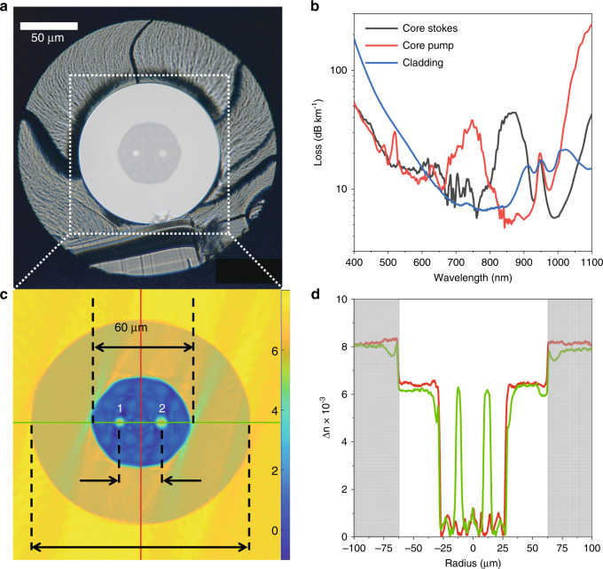
Fig. 1
DCDC fiber cross section, fiber attenuation and refractive index profile characterization.
a microscopic image of the front facet of the manufactured DCDC fiber consisting of two single-mode cores made of pure silica separated by 24 u00b5m and 4.8u2009u00b5m (core 1, cut-off wavelength 836u...
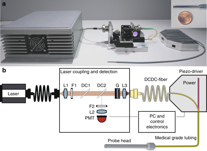
Fig. 2
Experimental set-up for multimodal non-linear DCDC fiber scanning CARS/SHG/TPEF endoscopy.
a Photo of the endomicroscopic fiber probe and laser coupling unit. A picture of the stainless steel shielded probe head of 2.4u2009mm diameter and a length of 39u2009mm is shown in the upper right co...
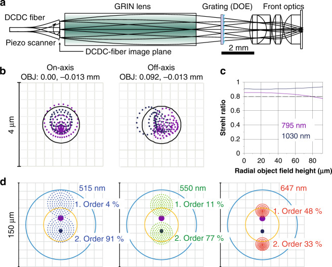
Fig. 3
Optical layout of the endomicroscopic objective and ray tracing results.
a Design scheme of the endomicroscopic objective consisting of a resonant piezo-scanner guided DCDC fiber, GRIN lens of 2.0u2009mm diameter, linear diffractive grating for combining pump and Stokes be...
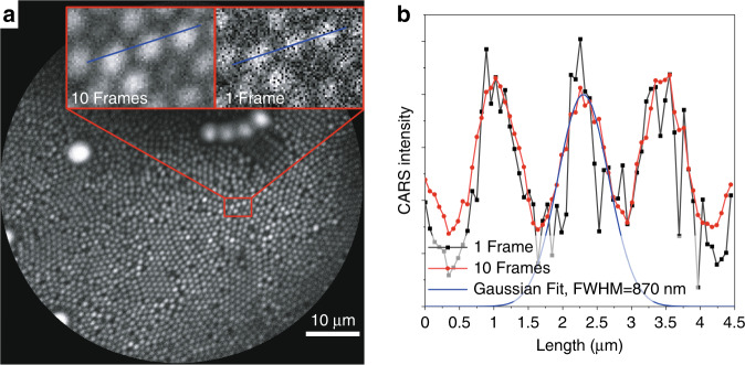
Fig. 4
Spatial resolution measurement of the endomicroscopic objective.
Resolution test with a mixture of polystyrene beads with a diameter of 1, 3, and 6u2009u00b5m at 70u2009u00b5m FoV ( a ) CARS image (10 frames average) of polystyrene beads at 2850u2009cm u22121 . The...
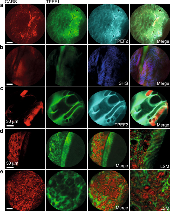
Fig. 5
Multimodal endoscopic images of unstained biological samples (first column CARS at 2850u2009cm u22121 in red, second column TPEF1 in green, third and fourth columns as indicated).
a Human epithelial tissue from the head and neck location CARS, TPEF1, and TPEF2 at 458u2009nm and combined image, thickness 15u2009u00b5m. Single epithelial cells and cell nuclei are resolved. b CARS...
Figure images are served from the NIH/NLM PubMed Central Open Access Subset or Europe PMC; copyright remains with the publishers and authors.
💬 Discussion
0 commentsNo comments yet. Be the first to start a discussion!
Leave a Comment