Abstract
Abstract Super‐resolution optical microscopy, which gives access to finer details of objects, is highly desired for fields of nanomaterial, nanobiology, nanophotonics, etc. Many efforts, including tip optimization and illumination optimization etc., have been made in both near‐field and far‐field super‐resolution microscopy to achieve a spatial resolution beyond the diffraction limit. The development of vector light fields opens up a new avenue for super‐resolution optical microscopy via special illumination modes. Cylindrical vector beam (CVB) has been verified to enable resolution improvement in tip‐scanning imaging, nonlinear imaging, stimulated emission depletion (STED) microscopy, subtraction imaging, superoscillation imaging, etc. This paper reviews recent advances in CVB‐based super‐resolution imaging. We start with an introduction of the fundamentals and properties of CVB. Next, strategies for CVB based super‐resolution imaging are discussed, which are mainly implemented by tight focusing, depletion effect, plasmonic nanofocusing, and polarization matching. Then, the roadmap of super‐resolution imaging with CVB illumination in the past two decades is summarized. The typical CVB‐based imaging techniques in fields of both near‐field and far‐field microscopy are introduced, including tip‐scanning imaging, nonlinear imaging, STED, subtraction imaging, and superoscillation imaging. Finally, challenges and future directions of CVB‐illuminated super‐resolution imaging techniques are discussed.
🔬 Techniques
✨ Fluorophores
🧪 Sample Preparation
🔬 Cell Lines
🏭 Microscope Brands
📷 Detectors
🏛️ Research Organizations (ROR)
Affiliated research institutions:
📊 Figures
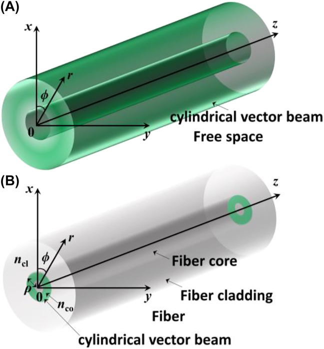
Figure 1:
Diagrams of CVBs. (A) Diagram of CVB in free space. (B) Diagram of CVB in fiber.
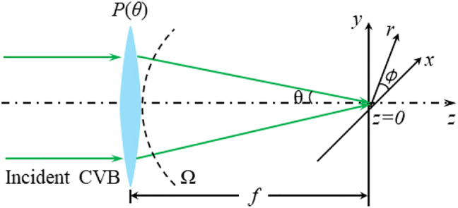
Figure 2:
Sketch map of the focusing process of RVB.
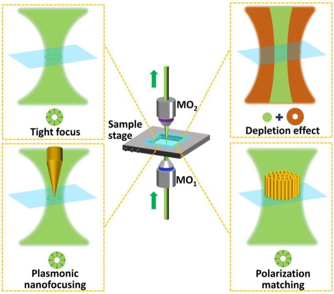
Figure 3:
Strategies for CVB-assisted super-resolution imaging.
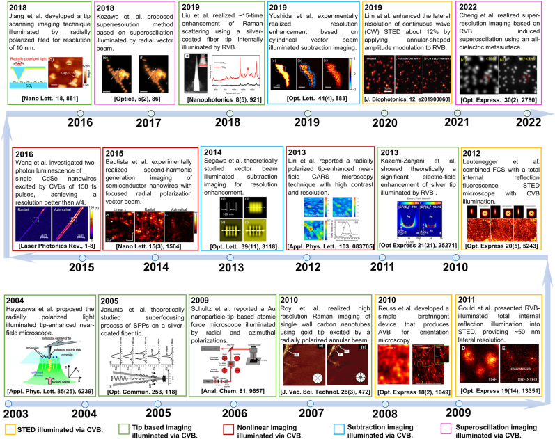
Figure 4:
Roadmap of the 20-year development of CVB-based super-resolution imaging from 2003 to 2022. Adapted from Ref. [ 37 ]. Copyright 2004 American Institute of Physics. Adapted from Ref. [ 38 ]. Copyright ...
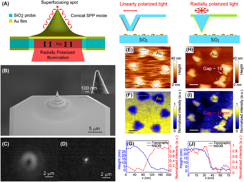
Figure 5:
Scanning near field imaging illuminated via RVB. (A) Principle of the super-focusing mode excitation at the tip apex under RVB illumination. (B) Scanning electron microscope (SEM) images of the Au-coa...
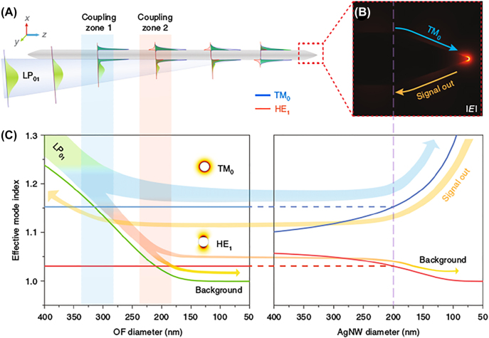
Figure 6:
Principle of linear fiber mode converting into SPP TM 0 mode by fiber taper integrated with a sharp Ag nanowire. (A) The phase-matching zones for linear fiber mode converting into SPP TM 0 mode. (B) S...
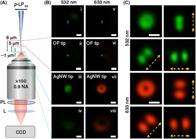
Figure 7:
Experimental verification of TM 0 mode excitation and nanofocusing. (A) Sketch map of high-magnification optical microscope for characterizing converter process of linear fiber mode (LP 01 ) to radial...
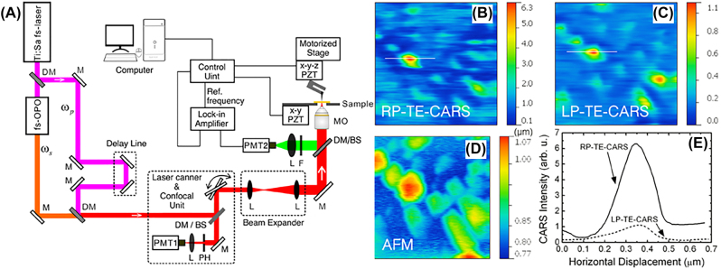
Figure 8:
Coherent anti-Stokes Raman scattering microscopy illuminated via CVB. (A) Schematic of the radially polarized tip-enhanced near-field CARS microscope. DM, dichroic mirror; L, lens; M, mirror; RP, radi...
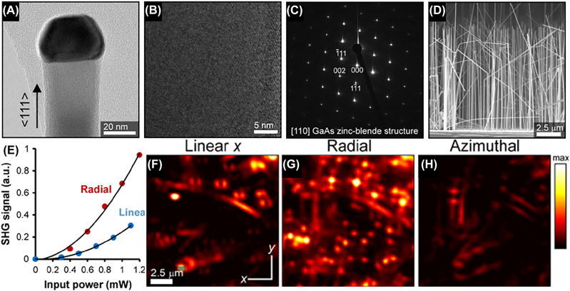
Figure 9:
Second-harmonic generation images of GaAs nanowires excited by CVB. (A, B) TEM characterizing results of a GaAs nanowire grown on a GaAs substrate. (C) Typical indexed ED pattern taken at different se...
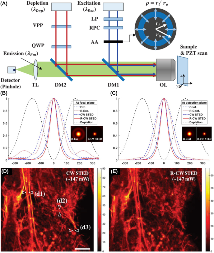
Figure 10:
RVB-illuminated CW STED microscopy. (A) Sketch map of RVB-illuminated CW STED microscopy. (B) Normalized PSF functions on the focal plane with the conventional illumination (circularly polarized), RVB...
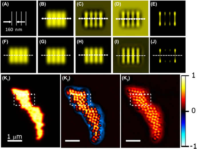
Figure 11:
Subtracting imaging illuminated via Gaussian-AVB and RP-AVB. (A) Sketch map of the simulation object. (Bu2013D) simulations of the subtraction imaging illuminated by Gaussian and AVB for u03b3 = 0, u0...
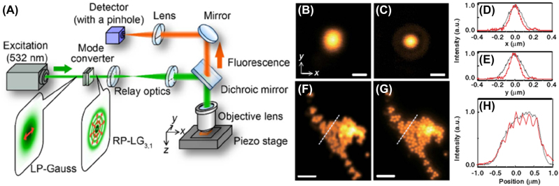
Figure 12:
Superoscillation imaging under RP-LG 3,1 illumination based on a confocal laser microscope. (A) Sketch map of superoscillation imaging system under RP-LG 3,1 illumination. (B) Measured PSFs (0.5 AU) f...
Figure images are served from the NIH/NLM PubMed Central Open Access Subset or Europe PMC; copyright remains with the publishers and authors.
💬 Discussion
0 commentsNo comments yet. Be the first to start a discussion!
Leave a Comment