Abstract
Cell cortex remodeling during cell division is a result of myofilament-driven contractility of the cortical membrane-bound actin meshwork. Little is known about the interaction between individual myofilaments and membrane-bound actin filaments. Here we reconstituted a minimal actin cortex to directly visualize the action of individual myofilaments on membrane-bound actin filaments using TIRF microscopy. We show that synthetic myofilaments fragment and compact membrane-bound actin while processively moving along actin filaments. We propose a mechanism by which tension builds up between the ends of myofilaments, resulting in compressive stress exerted to single actin filaments, causing their buckling and breakage. Modeling of this mechanism revealed that sufficient force (∼20 pN) can be generated by single myofilaments to buckle and break actin filaments. This mechanism of filament fragmentation and compaction may contribute to actin turnover and cortex reorganization during cytokinesis.DOI:http://dx.doi.org/10.7554/eLife.00116.001.
🔬 Techniques
🔭 Microscopes
💻 Software
✨ Fluorophores
🏭 Microscope Brands
🧪 Reagent Suppliers
🔎 Objectives
💻 Software Details
📋 Protocols
💾 Data Repositories
🏛️ Research Organizations (ROR)
Affiliated research institutions:
📋 Methods
Details of the experiments Traditionally, single muscle myosin II motors are described as non-processive motors ( Howard, 2001 ). By assembling myosin motors into filaments, the myofilaments become processive due to the coupling of a higher number of myosin heads that are in contact with the actin filament. In our minimal system directed movement accompanied by actin filament fragmentation only occurred at low ATP concentrations between 0.1–1 µM ( Figure 3 , Table 1 , Movie 3 ). The lower ATP concentrations are expected to increase the duration of the actin-bound post-working stroke state of the myosin head, thus increasing the duty ratio and processivity ( Howard, 2001 ). Extremely low ATP concentrations are on the other hand not sufficient for myosin motor activity. To check the effect of ATP concentration on processivity we added Alexa-647 labeled myofilaments to medium density MACs and tracked ( Rogers et al., 2007 ) the movement of individual myofilaments at low (1 µM) and high (4 mM) ATP concentrations ( Figure 5 , Movie 5 ). (Note that fragmentation and compaction of actin filaments only occurred at low ATP concentrations). Comparison of the trajectories illustrates that low ATP trajectories are on average longer than high ATP trajectories indicating a higher processivity at low ATP conditions ( Figure 5 , Movie 5 ). Moreover the number of tracked myofilaments at low ATP concentration with a dwell time greater than 900 ms was more than six times higher than at high ATP concentration suggesting a higher duty ratio at low ATP levels (n = 681 at low ATP, n = 102 at high ATP; Figure 5 , Movie 5 ). High ATP concentrations therefore lead to a faster detachment of myofilaments from actin filaments than at low ATP concentrations ( Movie 5 ). We propose that the increase in processivity due to ATP deprivation is necessary for the processive movement and a prerequisite for fragmentation and compaction of actin filaments.
Show full methods section
Details of the experiments Traditionally, single muscle myosin II motors are described as non-processive motors ( Howard, 2001 ). By assembling myosin motors into filaments, the myofilaments become processive due to the coupling of a higher number of myosin heads that are in contact with the actin filament. In our minimal system directed movement accompanied by actin filament fragmentation only occurred at low ATP concentrations between 0.1–1 µM ( Figure 3 , Table 1 , Movie 3 ). The lower ATP concentrations are expected to increase the duration of the actin-bound post-working stroke state of the myosin head, thus increasing the duty ratio and processivity ( Howard, 2001 ). Extremely low ATP concentrations are on the other hand not sufficient for myosin motor activity. To check the effect of ATP concentration on processivity we added Alexa-647 labeled myofilaments to medium density MACs and tracked ( Rogers et al., 2007 ) the movement of individual myofilaments at low (1 µM) and high (4 mM) ATP concentrations ( Figure 5 , Movie 5 ). (Note that fragmentation and compaction of actin filaments only occurred at low ATP concentrations). Comparison of the trajectories illustrates that low ATP trajectories are on average longer than high ATP trajectories indicating a higher processivity at low ATP conditions ( Figure 5 , Movie 5 ). Moreover the number of tracked myofilaments at low ATP concentration with a dwell time greater than 900 ms was more than six times higher than at high ATP concentration suggesting a higher duty ratio at low ATP levels (n = 681 at low ATP, n = 102 at high ATP; Figure 5 , Movie 5 ). High ATP concentrations therefore lead to a faster detachment of myofilaments from actin filaments than at low ATP concentrations ( Movie 5 ). We propose that the increase in processivity due to ATP deprivation is necessary for the processive movement and a prerequisite for fragmentation and compaction of actin filaments.
Details of the model
Biochemical cycle In the model of the myofilament interaction with actin, we assume that each active myosin head goes through the following biochemical cycle consisting of six head states ( Howard, 2001 ). The six states are schematized in Figure 8 . Unbound myosin head with ATP (state 1) hydrolyses ATP with the rate k 1 = 100 s −1 (state 2), binds to the actin filament with the rate k 2 = 30 s −1 (state 3), rapidly releases phosphate while performing a powerstroke with rate k 3 = 10 4 s −1 (state 4), releases ADP with the rate k 4 = 1000 s −1 (state 5), binds ATP with the rate k 5 = k t [ATP], where k t = 4 μM −1 s −1 , (state 6), and dissociates from the actin filament with the rate k 6 = 2000 s −1 (state 1). These rates determine the average time the myosin heads spend in every state ( Figure 9 ). In this simple model the rates are assumed to be independent of the strain of the myosin head. The myosin step size is d = 5 nm ( Howard, 2001 ). The myosin heads of the leading myofilament end always perform a step as a result of the powerstroke between the states 3 and 4. The heads of the trailing end either do not make a step (the probability of making a step p st =0), or, in separate simulations, make a step with the probability p st =0.1. This value is based on the observations that the trailing myofilament end moves along actin with approximately ten-times slower speed than the leading end ( Sellers and Kachar, 1990 ). Mechanical equillibrium Every myosin head attached to the actin filament is described as a spring with a spring constant equal to the myosin head stiffness κ = 1 pN nm −1 ( Kaya and Higuchi, 2010 ). After every step and after every detachment of a myosin head the forces are equilibrated by moving the myofilament along the actin filament. The result is a net movement of the whole myofilament towards the actin plus end, with flucuating tension force, velocity and number of attached myosin heads, the mean values of which depend on the ATP concentration. Number of myosin heads on the myofilament The median length of the myofilaments determined with AFM was 560 nm ( Figure 1C ). Assuming the length of the bare zone without myosin heads in the central part of the myofilament to be 160 nm ( Al-Khayat et al., 2010 ), both ends of the myofilament are 200 nm long. With four myosin head pairs around the myofilament circumference per every 14.5 nm ( Woodhead et al., 2005 ), there are on average 110 head pairs on each myofilament. Assuming further that only those heads oriented towards one side, that is, one quarter, can interact with the actin filament, and that only one head of the head pair is favorably oriented to interact, we estimate the average number of interacting heads as 30 per myofilament. Buckling force In order to estimate the force needed to bend the actin filament, we model it as a flexible rod with bending rigidity EI = 60 nN μm 2 , determined from the persistence length of actin: lp = EI/(kT) = 15 μm ( Yanagida et al., 1984 ). The force needed to buckle and break the filament is F = π 2 EI/l 2 . With the length l of the myofilament bare zone of 160 nm, this gives a force of 23 pN. Actin filaments break when the radius of curvature of a bent filament decreases below 0.18 μm ( Arai et al., 1999 ) corresponding to the curvature 1/r = 5.6 μm −1 .
Results of the simulations
In order to find out if the tension within the myofilament transferred onto the actin filament as a compressive force can become sufficiently high to bend and break the actin filament, we performed two types of simulations. In the first case, bending of the filament was not allowed and no limit was imposed on the compression force within the actin filament. This allowed us to determine the forces that can be reached by this model. In the second case, the actin filament was allowed to bend when the force of 23 pN was exceeded. Actin bending was modeled by decreasing the distance between the leading and trailing ends of the myofilament, thus relaxing the stress and reducing the force down to 23 pN. In case when bending was not allowed, the average force increased with decreasing ATP concentration, and also with the increasing number of myosin heads ( Figure 4A ). For 30 myosin heads, the force of 23 pN, neccessary to bend the filament, could be reached at ATP concentrations of approximately 3 µM or lower ( Figure 4A ). In the ATP concentration range used in the experiments here (2 ml reaction buffer to remove unbound Neutravidin. Then 10–50 µl of 2 µM (refers to monomers) Alexa-488-phalloidin labeled biotinylated actin filaments were added to the lipid bilayer and incubated for 1 h. The sample was carefully washed with approximately 1–2 ml reaction buffer to remove unbound actin filaments.
Actin fragmentation and pattern formation assay
Alexa-647 (and Alexa-488) labeled myofilaments and/or non-labeled myofilaments of various concentrations (as indicated) dissolved in 200 µl reaction buffer were added to the MAC and imaged by TIRF microscopy. The reaction buffer contained 0.1–1 µM ATP (see also Table 1 ), an ATP regenerating system consisting of 20 mM Creatine phosphate (Sigma) and 0.1 mg ml −1 Creatine phospho kinase (Sigma) to keep the ATP concentration constant and an oxygen scavenger system (glucose oxidase (165 U ml −1 ) catalase (2,170 U ml −1 ), β- D -glucose (0.4% wt/vol) and Trolox (2 mM), all from Sigma) to reduce photobleaching of the Alexa dyes. Actin rearrangements and fragmentation occurred immediately after addition of the myofilaments.
TIRF microscopy
Two color TIRF microscopy was carried out on a custom-made setup built around an Axiovert 200 microscope (Zeiss), for details see ( Loose et al., 2011 ). A α Plan-Apochromat 100×/NA 1.46 oil immersion objective and 488 nm and 647 nm laser lines were used for excitation of the labeled probes. The exposure times were either 50 ms or 100 ms, and the time intervals between each recorded frame ranged from 200–400 ms for different experiments.
AFM imaging
Atomic force microscopy was performed using a NanoWizard AFM system (JPK Instruments, Berlin, Germany). The AFM head was mounted on top of a stable cast-iron microscope stage and combined with a LSM 510 confocal microscope (Carl Zeiss, Jena, Germany). Soft, rectangular silicon cantilevers (CSC38/noAl, Micromash, Tallin, Estonia) with a nominal spring constant of 0.03 N/m were used. The cantilever sensitivity in V/m was determined before each measurement. The spring constant was calibrated by using the thermal fluctuations method. Clean, circular glass cover slips (d = 24 mm, #1.5, Menzel Gläser, Thermo Fisher, Braunschweig, Germany) were hydrophilized by air plasma cleaning. The AFM fluid cell was assembled by using the glass slide and filled with 400 µl of the reaction buffer. Directly before AFM imaging, myofilaments were diluted with reaction buffer to a concentration of 10 nM. 5 µL of 10 nM myofilaments in reaction buffer were added to the fluid cell. In experiments with combined AFM and fluorescence imaging, Alexa-488 labeled myofilaments were used. After 15 min incubation most of the myofilaments adhered to the hydrophilic surface, residual non-adherent filaments were removed by washing with reaction buffer. AFM imaging was performed in contact mode with a scan rate of 1 Hz. The imaging forces were kept very low (
📊 Figures
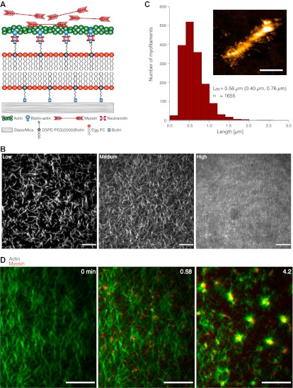
Figure 1.
MAC composition and actin pattern formation by myofilaments. ( A ) Scheme of the MAC. Biotinylated actin filaments are coupled to a supported lipid bilayer (Egg PC) containing biotinylated lipids (DSP...
Movie 1.
Actin pattern formation by myofilaments.
Medium density MAC containing Alexa-488-phalloidin labeled actin filaments (green) exhibits dynamic rearrangements of actin filaments after addition of myofilaments (0.3 u00b5M unlabeled myosin II dop...
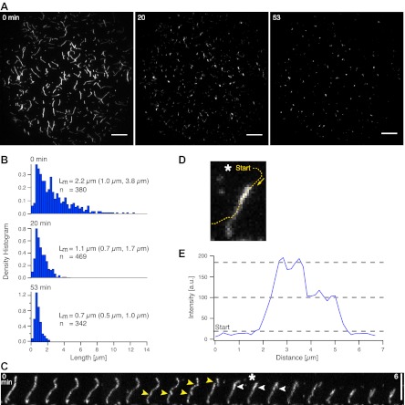
Figure 2.
Actin filament shortening and compaction by myofilaments. ( A ) TIRFM time-lapse images of a low actin density MAC with Alexa-488-phalloidin labeled actin filaments before (left image) and after addit...
Movie 2.
Shortening of individual actin filaments by myofilaments.
Individual Alexa-488-phalloidin labeled actin filaments in a low density MAC shorten over time in the presence of myofilaments. Original image sequence was acquired at 400 ms intervals and contained 8...
Movie 3.
Fragmentation of a single actin filament.
Example of a single Alexa-488-phalloidin labeled actin filament during its fragmentation and compaction in the presence of myofilaments. Images were acquired at 400 ms intervals. The video contains 14...
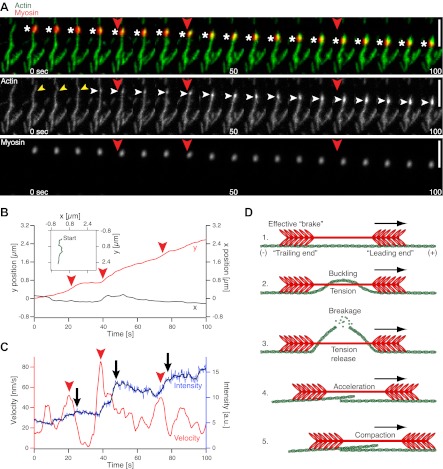
Figure 3.
Single molecule analysis of the myofilament movement and actin fragmentation. ( A ) Dual-color TIRFM time-lapse sequence of a Alexa-647 labeled myofilament (red) moving along an Alexa-488-phalloidin l...
Movie 4.
Movement and actin fragmentation by a single myofilament.
Example of a single Alexa-647 labeled myofilament during its directed movement along an Alexa-488-phalloidin labeled actin filament. During the movement the myofilament breaks and compacts the actin f...
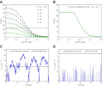
Figure 4.
Simulation of the interaction between myofilaments and an actin filament. ( A ) Mean tension force F within the myofilament when bending of actin is not allowed; dependence on ATP concentration for se...
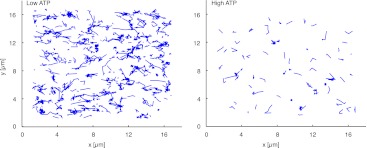
Figure 5.
Trajectories of individual myofilaments moving along actin filaments. Left panel displays the trajectories of myofilaments at low (1 u00b5M) ATP concentration (see also the corresponding Movie 5 ). Ri...
Movie 5.
Behavior of single myofilaments at low and high ATP concentrations.
The video shows the binding and moving behavior of Alexa-647 labeled myofilaments added to medium actin density MACs at low (1 u00b5M) and high (4 mM) ATP concentrations respectively. The white bar in...
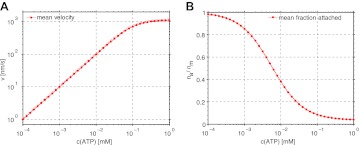
Figure 6.
Dependence of the mean velocity and mean number of attached myosin heads on the ATP concentration obtained from the simulations of myofilamentu2013actin filament interaction. ( A ) Mean velocity (poin...
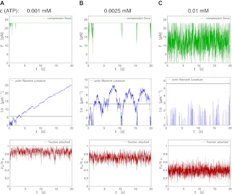
Figure 7.
Fluctuations of the compression force (upper row), the actin curvature (middle row) and the fraction of attached myosin heads (lower row) during 20 s of the simulation, for three different ATP concent...
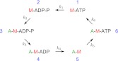
Figure 8.
The biochemical cycle of the myosin heads with rates k 1 u2013k 6 assumed in the model and the simulations. The rate k 5 is ATP-dependent. DOI: http://dx.doi.org/10.7554/eLife.00116.016
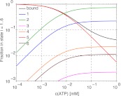
Figure 9.
The fractions of myosin heads in states 1u20136, and in the actin-bound state (sum of states 3u20136) in dependence on the ATP concentration. The values are calculated from the model of the myosin hea...
Figure images are served from the NIH/NLM PubMed Central Open Access Subset or Europe PMC; copyright remains with the publishers and authors.
💬 Discussion
0 commentsNo comments yet. Be the first to start a discussion!
Leave a Comment