Abstract
AbstractLabel‐free super‐resolution (LFSR) imaging relies on light‐scattering processes in nanoscale objects without a need for fluorescent (FL) staining required in super‐resolved FL microscopy. The objectives of this Roadmap are to present a comprehensive vision of the developments, the state‐of‐the‐art in this field, and to discuss the resolution boundaries and hurdles that need to be overcome to break the classical diffraction limit of the label‐free imaging. The scope of this Roadmap spans from the advanced interference detection techniques, where the diffraction‐limited lateral resolution is combined with unsurpassed axial and temporal resolution, to techniques with true lateral super‐resolution capability that are based on understanding resolution as an information science problem, on using novel structured illumination, near‐field scanning, and nonlinear optics approaches, and on designing superlenses based on nanoplasmonics, metamaterials, transformation optics, and microsphere‐assisted approaches. To this end, this Roadmap brings under the same umbrella researchers from the physics and biomedical optics communities in which such studies have often been developing separately. The ultimate intent of this paper is to create a vision for the current and future developments of LFSR imaging based on its physical mechanisms and to create a great opening for the series of articles in this field.
🔬 Techniques
✨ Fluorophores
🧪 Sample Preparation
🔬 Cell Lines
🏭 Microscope Brands
💻 Software Details
🏛️ Research Organizations (ROR)
Affiliated research institutions:
📋 Methods
5. Label-Free Plasmonic/Metamaterial Structured Illumination Microscopy (Junxiang Zhao, Zachary Burns, Zhaowei Liu* ) Structured illumination microscopy (SIM) doubles the resolution of a wide field fluorescent microscope and has seen many applications in biomedical studies. However, SIM provides no additional resolution enhancement over oblique illumination for label-free imaging due to the coherent nature of the scattering process. Meta-substrates using plasmonic structures and metamaterials provide a possibility to achieve illumination wave vectors beyond the limit of traditional optics, leading to a unique path for label-free super-resolution imaging. Here, we review the current super-resolution imaging techniques that combine SIM with meta-substrate assisted illuminations. We outline the challenges in achieving label-free super-resolution imaging and offer a set of directions for future work. Optical microscopy has been an irreplaceable tool in biomedical research but has a limited resolution due to the wave nature of the light. According to the Abbe diffraction limit of λ / 2 NA , where λ is the light wavelength and NA is the numerical aperture of the optics, the maximum spatial resolution of a conventional lens-based microscope at visible frequencies is around 200nm.
Numerous super-resolution microscopy
(SRM) techniques[ 224 – 226 ] has been developed for fluorescent microscopies to break the diffraction limit. Among these SRM techniques, structured illumination microscopy (SIM) [ 227 ] utilizes a series of periodic illumination patterns superimposed onto an object to improve the resolution by 2-fold. Compared to other SRM techniques, SIM’s advantages are its high imaging speed, wide field-of-view (FOV) and low photodamage, representing a nice combination for many biomedical applications.[ 228 ] However, since the scattering process is coherent, label-free imaging using scattered light gains little from structured illumination.[ 229 ] The bandwidths for detection and excitation are both limited within the coherent transfer function (CTF) using conventional optics. Therefore, for coherent label-free imaging, the structured illumination scheme does not yield any more information than imaging with oblique illuminations, which has a resolution well defined by the Abbe diffraction limit. SIM achieves super-resolution by frequency mixing the high spatial frequency components of the object into the detectable bandwidth of a microscope. The highest achievable resolution is determined by the sum of illumination and detection spatial frequencies: f = f d e t + f i l l u m . For a coherent imaging system with both illumination and detection cutoff frequency at NA / λ , the maximum attainable resolution is λ / 2 NA . Techniques like Fourier ptychography [ 230 ] use high angle oblique illumination combined with low NA objectives to achieve multiple fold resolution enhancement compared to the low NA resolution limit. But since the NA of oblique illuminations in free space cannot surpass 1, ultimately such methods cannot achieve higher resolution than the Abbe diffraction limit of high NA optics. Since optical microscopes typically require far-field detection, the detection bandwidth cannot be further improved other than using objectives with the highest available NA. Therefore, creating higher spatial frequency illumination patterns is the most viable and crucial approach to achieving label-free super-resolution SIM. Plasmonic structures and hyperbolic metamaterials are known for supporting larger wavevector waves compared to dielectric medium and have seen many applications in sub-wavelength imaging and sensing.[ 231 – 233 ] By introducing a meta-substrate designed with a plasmonic nanostructure or metamaterial to generate illuminations, metamaterial assisted illumination nanoscopy (MAIN) can achieve much higher resolution than standard SIM methods.[ 234 ] One way to create illuminations beyond the diffraction-limit is to use a meta-substrate containing plasmonic nanostructures. Plasmonic structured illumination microscopy (PSIM)[ 235 ] and localized plasmonic structured illumination microscopy (LPSIM)[ 236 , 237 ] use interference patterns from counter propagating surface plasmon polaritons (SPP) and localized surface plasmon (LSP) waves from metallic nano-disc arrays to generate illuminations beyond the traditional diffraction-limit respectively. Figure 7a illustrates the lateral wavevector comparison for propagating light, PSIM illumination and LPSIM illumination. Contrary to traditional SIM, the maximum achievable bandwidths for PSIM and LPSIM with fluorescent imaging are described by k P S I M = 2 k S P P + 2 N A × k 0 and k L P S I M = k L S P + 2 N A × k 0 , where k S P P and k L S P are the wavevectors of PSIM and LPSIM illumination patterns, and k 0 is the free space wavevector of the illumination wavelength ( Figure 7b ). Compared to the diffraction-limit, PSIM has experimentally demonstrated ~2.6-fold resolution improvement[ 235 ] and LPSIM has demonstrated 3-fold resolution improvement for biological samples.[ 236 , 237 ] For a coherent label-free imaging system with CTF cutoff frequency at NA / λ , the illuminations from PSIM and LPSIM are purely dependent on the nanostructures and thus can achieve higher resolution beyond the diffraction limit described by: k P S I M / L P S I M = k S P P / L S P + N A × k 0 ( Figure 7c ). At this moment, however, the experimental demonstration of label-free PSIM and LPSIM has yet to be done. Hyperbolic metamaterials (HMM) have recently been used as meta-substrates for ultra-high resolution optical imaging.[ 238 – 240 ] Figure 8a – b show that an ideal HMM can support arbitrarily large lateral wavevectors as the isofrequency surface of an HMM is a two-sheet hyperboloid for a Type I HMM ( ε ⊥ > 0 , ε ∥ < 0 ) or a one-sheet hyperboloid for a Type II HMM ( ε ⊥ < 0 , ε ∥ > 0 ). HMMs are commonly implemented by two types of structures: a lattice of metallic nanorods embedded in a dielectric medium or a stack of deep subwavelength alternatingmetallic and dielectric layers. For imaging applications, the multilayer structures are the most practical methods to implement the HMMs. A practical HMM consists of multiples layers of metal and dielectric films can support extremely large lateral wavevectors[ 241 ] in the near field, thus they can create high resolution illumination patterns ( Figure 8c ). One implementation of HMM assisted illumination microscopy is hyper-structured illumination [ 239 , 240 ], which utilizes the highly dispersive nature of an HMM to project a series of deep-subwavelength illumination patterns which are tuned by the incident wavelength. A 6-fold resolution improvement over the diffraction limit has been reported for hyper-structured illumination with label-free imaging, resolving features down to ~80 nm.[ 240 ] Another implementation of MAIN, named speckle-MAIN,[ 241 ] creates deep sub-wavelength speckle illumination patterns by taking advantage of the inherent material roughness within the multilayer HMM ( Figure 8d ) and achieves 40 nm resolution with a fluorescent microscope. Recently, novel organic hyperbolic metamaterials (OHM) fabricated by self-assembled regioregular poly(3-hexylthiophene-2,5-diyl) have been demonstrated to support remarkably large lateral wavevector in the visible frequencies. [ 242 , 243 ] The OHM assisted MAIN produces ultra-high resolution of 30 nm while exhibiting superior biocompatibility and photostability due to its exceptionally large Purcell factor at the film surface.[ 243 , 244 ] One of the main challenges of label-free super-resolution imaging is the low photon budget due to the very weak scattering of sub-wavelength objects. The resulting low signal-to-noise ratio (SNR) causes significant loss of high-resolution information as higher spatial frequency components of an object typically have very low spatial spectrum density. Recently, plasmonic scattering imaging [ 245 ] demonstrated imaging of single proteins by using a thin gold film as the sample substrate. With a meta-substrate, significant enhancement of scattering from small objects greatly improves the SNR and allows for far-field detection. This is especially crucial for imaging tiny objects with a target resolution of sub-50 nm, as the scattering cross-section is too small to create a meaningful measurement with traditional imaging methods. Image reconstruction has also been a major roadblock for realizing label-free MAIN. Fluorescent versions of MAIN that rely on intensity fluctuation based reconstruction methods [ 246 – 248 ] have shown promising imaging results. However, since scattering is a coherent process, the label-free imaging system is linear with respect to the electric field rather than the intensity. As we detect only the intensity with a camera, an ill-posed non-linear inverse problem must be solved to retrieve the object information. One method to overcome this problem is to use a meta-substrate made of turbid medium and record the transmission matrix of all near-field input modes at the cost of requiring near-field scanning of the entire FOV prior to imaging. The far-field scattered light of the object will be a linear combination of the basis transmission matrix such that a super-resolution image can be retrieved by time reversal reconstruction.[ 249 ] Increasingly deep neural networks are being used for super resolution microscopy reconstruction [ 250 , 251 ] to boost performance over traditional methods, for example by reducing the number of sub-frames and handling cases of low signal-to-noise ratio. Often there is knowledge of the physical system that could be incorporated into the network to reduce the training burden and improve results.[ 252 ] Recently there has been the development of “physics-based” or “untrained” neural networks that incorporate a physical forward model into the loss function for training. These methods have been applied to cases such as phase imaging and lensless imaging. [ 253 – 255 ] For label-free MAIN, where the illumination field and forward process is known, there is the potential to incorporate this knowledge into a physics-based network trained on a collection of data. Such a model could combine the benefits of a traditional physics-based model with those of statistical learning to create better reconstructions and alleviate some of the challenges of the ill-posed inverse problem. Current label-free MAIN results are, at this point, mostly preliminary. Hyper-structured illumination has achieved label-free super-resolution for a 1D object, but its 2D imaging capability has not been demonstrated. PSIM, LPSIM and speckle-MAIN have only been experimentally demonstrated with fluorescent imaging and a robust image reconstruction scheme for coherent imaging has yet to be developed. Nevertheless, MAIN addresses the major difficulties in achieving super-resolution label-free imaging with its exceptionally larger illumination bandwidth and SNR improvement over traditional optics.
Show full methods section
5. Label-Free Plasmonic/Metamaterial Structured Illumination Microscopy (Junxiang Zhao, Zachary Burns, Zhaowei Liu* ) Structured illumination microscopy (SIM) doubles the resolution of a wide field fluorescent microscope and has seen many applications in biomedical studies. However, SIM provides no additional resolution enhancement over oblique illumination for label-free imaging due to the coherent nature of the scattering process. Meta-substrates using plasmonic structures and metamaterials provide a possibility to achieve illumination wave vectors beyond the limit of traditional optics, leading to a unique path for label-free super-resolution imaging. Here, we review the current super-resolution imaging techniques that combine SIM with meta-substrate assisted illuminations. We outline the challenges in achieving label-free super-resolution imaging and offer a set of directions for future work. Optical microscopy has been an irreplaceable tool in biomedical research but has a limited resolution due to the wave nature of the light. According to the Abbe diffraction limit of λ / 2 NA , where λ is the light wavelength and NA is the numerical aperture of the optics, the maximum spatial resolution of a conventional lens-based microscope at visible frequencies is around 200nm.
Numerous super-resolution microscopy
(SRM) techniques[ 224 – 226 ] has been developed for fluorescent microscopies to break the diffraction limit. Among these SRM techniques, structured illumination microscopy (SIM) [ 227 ] utilizes a series of periodic illumination patterns superimposed onto an object to improve the resolution by 2-fold. Compared to other SRM techniques, SIM’s advantages are its high imaging speed, wide field-of-view (FOV) and low photodamage, representing a nice combination for many biomedical applications.[ 228 ] However, since the scattering process is coherent, label-free imaging using scattered light gains little from structured illumination.[ 229 ] The bandwidths for detection and excitation are both limited within the coherent transfer function (CTF) using conventional optics. Therefore, for coherent label-free imaging, the structured illumination scheme does not yield any more information than imaging with oblique illuminations, which has a resolution well defined by the Abbe diffraction limit. SIM achieves super-resolution by frequency mixing the high spatial frequency components of the object into the detectable bandwidth of a microscope. The highest achievable resolution is determined by the sum of illumination and detection spatial frequencies: f = f d e t + f i l l u m . For a coherent imaging system with both illumination and detection cutoff frequency at NA / λ , the maximum attainable resolution is λ / 2 NA . Techniques like Fourier ptychography [ 230 ] use high angle oblique illumination combined with low NA objectives to achieve multiple fold resolution enhancement compared to the low NA resolution limit. But since the NA of oblique illuminations in free space cannot surpass 1, ultimately such methods cannot achieve higher resolution than the Abbe diffraction limit of high NA optics. Since optical microscopes typically require far-field detection, the detection bandwidth cannot be further improved other than using objectives with the highest available NA. Therefore, creating higher spatial frequency illumination patterns is the most viable and crucial approach to achieving label-free super-resolution SIM. Plasmonic structures and hyperbolic metamaterials are known for supporting larger wavevector waves compared to dielectric medium and have seen many applications in sub-wavelength imaging and sensing.[ 231 – 233 ] By introducing a meta-substrate designed with a plasmonic nanostructure or metamaterial to generate illuminations, metamaterial assisted illumination nanoscopy (MAIN) can achieve much higher resolution than standard SIM methods.[ 234 ] One way to create illuminations beyond the diffraction-limit is to use a meta-substrate containing plasmonic nanostructures. Plasmonic structured illumination microscopy (PSIM)[ 235 ] and localized plasmonic structured illumination microscopy (LPSIM)[ 236 , 237 ] use interference patterns from counter propagating surface plasmon polaritons (SPP) and localized surface plasmon (LSP) waves from metallic nano-disc arrays to generate illuminations beyond the traditional diffraction-limit respectively. Figure 7a illustrates the lateral wavevector comparison for propagating light, PSIM illumination and LPSIM illumination. Contrary to traditional SIM, the maximum achievable bandwidths for PSIM and LPSIM with fluorescent imaging are described by k P S I M = 2 k S P P + 2 N A × k 0 and k L P S I M = k L S P + 2 N A × k 0 , where k S P P and k L S P are the wavevectors of PSIM and LPSIM illumination patterns, and k 0 is the free space wavevector of the illumination wavelength ( Figure 7b ). Compared to the diffraction-limit, PSIM has experimentally demonstrated ~2.6-fold resolution improvement[ 235 ] and LPSIM has demonstrated 3-fold resolution improvement for biological samples.[ 236 , 237 ] For a coherent label-free imaging system with CTF cutoff frequency at NA / λ , the illuminations from PSIM and LPSIM are purely dependent on the nanostructures and thus can achieve higher resolution beyond the diffraction limit described by: k P S I M / L P S I M = k S P P / L S P + N A × k 0 ( Figure 7c ). At this moment, however, the experimental demonstration of label-free PSIM and LPSIM has yet to be done. Hyperbolic metamaterials (HMM) have recently been used as meta-substrates for ultra-high resolution optical imaging.[ 238 – 240 ] Figure 8a – b show that an ideal HMM can support arbitrarily large lateral wavevectors as the isofrequency surface of an HMM is a two-sheet hyperboloid for a Type I HMM ( ε ⊥ > 0 , ε ∥ < 0 ) or a one-sheet hyperboloid for a Type II HMM ( ε ⊥ < 0 , ε ∥ > 0 ). HMMs are commonly implemented by two types of structures: a lattice of metallic nanorods embedded in a dielectric medium or a stack of deep subwavelength alternatingmetallic and dielectric layers. For imaging applications, the multilayer structures are the most practical methods to implement the HMMs. A practical HMM consists of multiples layers of metal and dielectric films can support extremely large lateral wavevectors[ 241 ] in the near field, thus they can create high resolution illumination patterns ( Figure 8c ). One implementation of HMM assisted illumination microscopy is hyper-structured illumination [ 239 , 240 ], which utilizes the highly dispersive nature of an HMM to project a series of deep-subwavelength illumination patterns which are tuned by the incident wavelength. A 6-fold resolution improvement over the diffraction limit has been reported for hyper-structured illumination with label-free imaging, resolving features down to ~80 nm.[ 240 ] Another implementation of MAIN, named speckle-MAIN,[ 241 ] creates deep sub-wavelength speckle illumination patterns by taking advantage of the inherent material roughness within the multilayer HMM ( Figure 8d ) and achieves 40 nm resolution with a fluorescent microscope. Recently, novel organic hyperbolic metamaterials (OHM) fabricated by self-assembled regioregular poly(3-hexylthiophene-2,5-diyl) have been demonstrated to support remarkably large lateral wavevector in the visible frequencies. [ 242 , 243 ] The OHM assisted MAIN produces ultra-high resolution of 30 nm while exhibiting superior biocompatibility and photostability due to its exceptionally large Purcell factor at the film surface.[ 243 , 244 ] One of the main challenges of label-free super-resolution imaging is the low photon budget due to the very weak scattering of sub-wavelength objects. The resulting low signal-to-noise ratio (SNR) causes significant loss of high-resolution information as higher spatial frequency components of an object typically have very low spatial spectrum density. Recently, plasmonic scattering imaging [ 245 ] demonstrated imaging of single proteins by using a thin gold film as the sample substrate. With a meta-substrate, significant enhancement of scattering from small objects greatly improves the SNR and allows for far-field detection. This is especially crucial for imaging tiny objects with a target resolution of sub-50 nm, as the scattering cross-section is too small to create a meaningful measurement with traditional imaging methods. Image reconstruction has also been a major roadblock for realizing label-free MAIN. Fluorescent versions of MAIN that rely on intensity fluctuation based reconstruction methods [ 246 – 248 ] have shown promising imaging results. However, since scattering is a coherent process, the label-free imaging system is linear with respect to the electric field rather than the intensity. As we detect only the intensity with a camera, an ill-posed non-linear inverse problem must be solved to retrieve the object information. One method to overcome this problem is to use a meta-substrate made of turbid medium and record the transmission matrix of all near-field input modes at the cost of requiring near-field scanning of the entire FOV prior to imaging. The far-field scattered light of the object will be a linear combination of the basis transmission matrix such that a super-resolution image can be retrieved by time reversal reconstruction.[ 249 ] Increasingly deep neural networks are being used for super resolution microscopy reconstruction [ 250 , 251 ] to boost performance over traditional methods, for example by reducing the number of sub-frames and handling cases of low signal-to-noise ratio. Often there is knowledge of the physical system that could be incorporated into the network to reduce the training burden and improve results.[ 252 ] Recently there has been the development of “physics-based” or “untrained” neural networks that incorporate a physical forward model into the loss function for training. These methods have been applied to cases such as phase imaging and lensless imaging. [ 253 – 255 ] For label-free MAIN, where the illumination field and forward process is known, there is the potential to incorporate this knowledge into a physics-based network trained on a collection of data. Such a model could combine the benefits of a traditional physics-based model with those of statistical learning to create better reconstructions and alleviate some of the challenges of the ill-posed inverse problem. Current label-free MAIN results are, at this point, mostly preliminary. Hyper-structured illumination has achieved label-free super-resolution for a 1D object, but its 2D imaging capability has not been demonstrated. PSIM, LPSIM and speckle-MAIN have only been experimentally demonstrated with fluorescent imaging and a robust image reconstruction scheme for coherent imaging has yet to be developed. Nevertheless, MAIN addresses the major difficulties in achieving super-resolution label-free imaging with its exceptionally larger illumination bandwidth and SNR improvement over traditional optics.
24. Microsphere Superlens and Metamaterial Solid Immersion Lens (Zengbo Wang*, Boris Luk’yanchuk, Limin Wu) 24.1 Status In 2011, super-resolution imaging by microsphere superlens emerged as a simple yet effective method to overcome the diffraction limit that limits the resolution of conventional lenses.[ 698 ] Significant progress has since been made. Here, key advances including the development of scanning superlens system, metamaterial solid immersion lens (mSIL), super-resolution physics and bio-superlens are discussed along with the challenges in this field. For more detailed review on the technique and other superlens applications in interferometry, endoscopy, and others, please refer to refs. [ 699 , 700 ] 24.2. Microsphere Nanoscopy: 24.2.1. Overview: The field of microsphere superlens research dates back to 2000 when it was discovered that a microsphere could generate subwavelength focus.[ 701 ] This effect became known as ‘photonic nanojet (PNJ)’ since 2004 and was widely used in laser cleaning, laser direct nano-writing and signal enhancement[ 700 ], among other applications. The achievement of 80 nm resolution in laser patterning by microsphere [ 702 ] motivated the research on microsphere nanoscopy, first published in 2011. [ 698 ] As shown in Figure 45(a) , the technique uses microsphere as superlens to image the contacting nanoscale objects. The superlens collects and transforms the near-field evanescent waves, which carry the high-spatial-frequency information about the object, into the propagating waves reaching the far-field and leading to a formation of a magnified virtual image. The evanescent-to-propagating-conversion (ETPC) efficiency determines the final imaging resolution. [ 703 ] Further improvement of the resolution can be accomplished by enhancing the ETPC efficiency. These ideas motivated the development of the mSIL superlens discussed below, which provides improved ETPC efficiency with enhanced optical super-resolution and imaging quality. [ 704 ] In contact mode, the microsphere superlens can resolve 50–100 nm scale objects (e.g., nanostructures and devices ( Figure 45 ), subcellar structures and adenovirus [ 705 ]) using a wide-field microscope. Smaller features, i.e., 15–25 nm nanogaps, can be resolved with superlens under a confocal microscope. [ 706 , 707 ] Since resolution of an imaging system is often characterized by the point spread function (PSF) instead of by the minimal resolvable feature sizes, Allen et. al. developed a convolution-based resolution analysis method and derived the best resolution for microsphere nanoscopy is ∼ λ / 6 − λ / 7 ( Figure 45b ). [ 706 ] A higher estimation for resolution of λ / 8 could be obtained if the final image’s contrast is adjusted for clarity before convolution, giving calibrated resolution of ∼ λ / 6 − λ / 8 for the technique. Such method is now widely used to calculate the PSF resolution for the superlens, which avoids exaggerated resolution claim beyond λ / 10 based on the minimal resolvable feature sizes. In non-contact mode, resolution of the superlens drops rapidly when particle-sample distance Δ z increases, from λ / 7 at Δ z = 0 (contacting) to λ / 3.8 at Δ z ≈ λ / 2 (half wavelength). Super-resolution typically degrades if the distance exceeds one wavelength. Extending the working distance (WD) of a superlens is a major challenge for this technique which is discussed later. A variety of microspheres have been used as superlenses for imaging, including BaTiO 3 (BTG), Polystyrene (PS) and SiO 2 microspheres with typical size between 3 and 80 μm. For an optimum imaging, the optical contrast (OC, i.e., refractive index ratio between microsphere and surrounding media) is recommended within 1.4–1.75. [ 698 , 708 ] Therefore, for high-index microspheres such as BTG (n = 1.9–2.1) and others, an immersion media (e.g., water or transparent resin) is often used to optimize the OC to maximize the performance. 24.2.2. Scanning Superlens The ability to position microsphere superlens at desired location and scanning over an area are essential for practical applications. Single microsphere has a narrow field-of-view (FOV), scanning is utilized to expand FOV for imaging larger-area and for dynamic imaging. Several scanning schemes have been demonstrated, such as integration with AFM system [ 709 ] and encapsulation of microsphere in solid film. [ 706 ] Figure 45(c) shows the AFM-based scanning superlens system built by attaching a microsphere to an AFM tip and use precision motion system of AFM to control particle-sample distance and scanning across the sample surface. The system can work in both contact and non-contact scanning modes. A 96 × 96 μm 2 sized sample image was obtained in 3 mins with super-resolution at λ / 6.3 level for 80–90 nm objects, which is about 200 times faster compared to the ordinary AFM. Another scanning approach is to bond the microsphere directly with the objective lens to form a unibody design, [ 710 ] which was used in commercial microsphere nanoscope developments. [ 711 ] The resolution of commercial systems can be at ~137–150 nm (measured by PSF) due to difficulties of attaining contact scanning mode. 24.2.3. Super-Resolution Physics A complete theory for microsphere nanoscopy is still under development and one of the latest results is the wave theory of virtual imaging by microsphere. [ 712 ] The mechanism behind microsphere nanoscopy has been under debate since its birth. The PNJ effect was first considered as the main mechanism. However, calculations show that super-resolution strength by PNJ is weak, typically ∼ λ / 2 − λ / 3 for n = 1.5–1.6 particles. To explain the strong super-resolution ∼ λ / 6 − λ / 8 observed in experiments, other mechanisms were studied. Excitation of whispery gallery mode (WGM) in microsphere allows to explain resolution up to λ / 4 . Very recently, new super-resonance (SR) modes in microsphere were discovered. [ 713 ] A typical SR mode field distribution is shown in Figure 45(d) . It has a pair of highly localized hotspots ( | E | 2 > 10 4 − 10 5 , three orders higher than PNJ of 10–10 2 ) near the bottom and top apex of the microsphere. A strong resolution of ∼ λ / 3 − λ / 6 is observed in Fig 45(d) . Deeper resolution and stronger field enhancement (10 9 –10 11 ) [ 714 ] by SR effect is possible for other particles, which requires further investigates. Moreover, some other mechanisms also contribute to resolution enhancement, such as plasmonic substrate effect and non-traditional illumination method (e.g., partial and inclined illumination [ 709 , 715 ] and near-field evanescent-wave illumination using fluorescent nanowire [ 716 ] and localized plasmonic structured illumination [ 717 ]). 24.2.4. Bio-Superlens Another trend in the field is the development of biological superlens using biomaterials such as spider silks, [ 718 ] cyanobacteria, live yeast cells,[ 719 ], and lipid droplets,[ 720 ] where typically 100 nm features can be resolved (not PSF). These bio-superlenses may open the intriguing route for developing multifunctional biocompatible bioimaging tools for sensing and single-cell diagnosis, which will be further advanced in future. 24.3. Metamaterial Solid Immersion Lens (mSIL): A notable achievement in the field is the development of mSIL in 2016. mSIL is an artificially engineered three-dimensional all-dielectric superlens assembled by high-index nanoparticles ( Figure 46 ) that supports enhanced ETPC efficiency. Exploiting 15 nm high-index ( n = 2.55 ) TiO 2 nanoparticles as building blocks, we fabricated TiO 2 mSIL with widths of 10–20 μm ( Figure 46a ) and demonstrated excellent super-resolution performance. It generates a sharp image with a resolution of at least 45 nm ( ≈ λ / 8.5 PSF resolution, Figure 46c ), which exceeds the resolution of all previous superlenses. A new super-resolution mechanism was discovered in mSIL. The near-field coupling between neighbouring nanoparticles in closely stacked media can effectively guide and transform the propagating wave into a large-area array of structured evanescent wave illumination field ( Figure 46b ). Inversely, the composite media supports highly efficient ETPC that lead to enhanced super-resolution. Similar works have been reported using other materials like ZrO 2 to replace TiO 2 [ 721 ]. Recently, Dhama et al. designed and fabricated full-sphere TiO 2 mSIL and compared the imaging performance with BTG microsphere. The results confirmed that mSIL superlens performs consistently better than BTG superlens in terms of imaging contrast, sharpness, clarity, field of view and resolution. [ 722 ] Besides mSIL, gradient solid immersion lenses (Maxwell fisheye) may provide another route towards near-perfect super-resolution imaging. [ 723 , 724 ] 24.4. Current and Future Challenges The imaging contrast by microsphere nanoscopy is often low due to the relatively weak ETPC efficiency. The low-contrast problem can be partially solved by mSIL with enhanced ETPC. While mSIL has shown greater imaging resolution and quality over other superlenses, its structure-integrity, lifetime in air/liquid and suitability for scanning imaging remains unknown which demands more investigations. Increasing WD in dielectric superlens nanoscopy while retaining super-resolution is a key challenge in the field. Using partial and inclined illumination have shown the possibility to extend the working distance from sub-wavelength scale to more than one wavelength scale. [ 709 ] Other proposals are needed to extend WD to at least 5 μm scale to enable a truly 3D super-resolution imaging of biological details and processes. Developing a higher speed nanoscopy system remains another challenge for the technique. Deeper tissue imaging, and combination of superlens with other super-resolution techniques (e.g., fluorescent nanoscopy) to achieve multi-modal super-resolution imaging systems will also be the future challenge for the technique. 24.5. Advances in Science and Technology to Meet Challenges Recent advances in photonics, nanomaterials, metamaterials, and artificial intelligence (AI) could be utilized to address the discussed challenges. Introducing superlenses like microsphere/mSIL into a conventional optical microscope system leads to unwanted aberrations that reduce imaging contrast and quality, despite the resolution is improved locally at a region under the microsphere. This contradiction could be solved by using adaptive optics technology to correct the aberrations so that high-contrast super-resolution image can be obtained. [ 725 ] Another possible solution is to use metasurface, which can be designed and placed in front of the dielectric superlenses to realize similar function to the adaptive optics. Highly tuneable Metamaterials and metasurfaces will also be the promising solution to enable the development of long-WD superlens due to its flexibility in phase, amplitude, polarization, and wavefront engineering. [ 726 ] Combining superlenses with multiphoton microscopy may offer another solution to develop a long-WD superlens imaging system, e.g., using nonlinear effect to enhance resolution at the far-field zones. Due to significant amount of data generated during scanning superlens over a large-area, AI and machine learning technologies are particularly useful to process the big data to generate desired output image or extract features from a large-image. The latter property is especially useful for developing systems capable of tracking dynamics in biological samples. 24.6. Conclusions Dielectric superlenses made from microsphere and nanoparticles and other materials have proven to be the effective tools to overcome the diffraction limit. Optical super-resolution of ∼ λ / 6 − λ / 8 (measured by PSF) has been demonstrated in real-time, label-free imaging of a variety of samples and processes in fields such as biology, material, and medicine research. The superlens technology has the potential to revolutionize the field of optical microscopy when the discussed challenges are resolved.
24.3. Metamaterial Solid Immersion Lens (mSIL): A notable achievement in the field is the development of mSIL in 2016. mSIL is an artificially engineered three-dimensional all-dielectric superlens assembled by high-index nanoparticles ( Figure 46 ) that supports enhanced ETPC efficiency. Exploiting 15 nm high-index ( n = 2.55 ) TiO 2 nanoparticles as building blocks, we fabricated TiO 2 mSIL with widths of 10–20 μm ( Figure 46a ) and demonstrated excellent super-resolution performance. It generates a sharp image with a resolution of at least 45 nm ( ≈ λ / 8.5 PSF resolution, Figure 46c ), which exceeds the resolution of all previous superlenses. A new super-resolution mechanism was discovered in mSIL. The near-field coupling between neighbouring nanoparticles in closely stacked media can effectively guide and transform the propagating wave into a large-area array of structured evanescent wave illumination field ( Figure 46b ). Inversely, the composite media supports highly efficient ETPC that lead to enhanced super-resolution. Similar works have been reported using other materials like ZrO 2 to replace TiO 2 [ 721 ]. Recently, Dhama et al. designed and fabricated full-sphere TiO 2 mSIL and compared the imaging performance with BTG microsphere. The results confirmed that mSIL superlens performs consistently better than BTG superlens in terms of imaging contrast, sharpness, clarity, field of view and resolution. [ 722 ] Besides mSIL, gradient solid immersion lenses (Maxwell fisheye) may provide another route towards near-perfect super-resolution imaging. [ 723 , 724 ]
📊 Figures

Figure 1.
Tree diagram of evolutionary development of LFSR subjects and methods.
The tree is rooted in a classical diffraction limit introduced by Abbe, Helmholtz, and Rayleigh. The stem (4) represents development of Mainstream diffraction-limited microscopy due to incorporation o...

Figure 2:
Super-resolved reconstruction of a simulated tubulins dataset [ 161 ], composed of 361 high-density frames.
(a,b): SPARCOM reconstruction, executed over 100 iterations with (a) unknown PSF (assuming a dirac delta PSF) and u03bb = 0.0105 , (b) the correct PSF and u03bb = 0.13 . (c): LSPARCOM reconstruction. ...

Figure 3:
Super-resolved reconstruction of an experimental tubulins dataset [ 161 ], composed of 15 000 low-density frames.
The frames were summed in groups of 50, resulting in a high-density sequence of 300 frames, on which the super-resolved reconstructions were performed. (a,b): SPARCOM reconstruction, executed over 100...

Figure 4.
DL-SR microscopy and commonly employed DNN architectures.
(a) DL-SR microscopy digitally transforms a LR image obtained by a diffraction-limited microscope to match the corresponding HR image of the same specimen that is acquired by a SR microscopy modality....

Figure 5.
Applications of DL-SR optical microscopy.
(a) STORM, SIM, PALM, and Fourier ptychographic microscopy (FPM). (b) Single-image super-resolution in wide-field fluorescence, bright-field and digital holographic microscopy.

Figure 6.
Deeply Subwavelength Topological Metrology and Microscopy
with a topologically structured (e.g. superoscillatory) light field (following [ 222 , 223 ]). The intensity profile of the diffraction pattern resulting from scattering of the topologically structure...

Figure 7.
Concept of resolution enhancement with PSIM and LPSIM
(a) The dispersion relation comparison of a propagating photon in dielectric media, a SPP at dielectric/metal interfaces and the LSP field from a nanoantenna array. The wavevectors at the illumination...

Figure 8.
HMM for super-resolution imaging.
(a) The isofrequency surface for a Type I HMM ( u03b5 u22a5 > 0 , u03b5 u2225 < 0 ). Type I HMMs are commonly achieved with nanorod arrays. (b) The isofrequency surface for a Type II HMM ( u03b5 u2...

Figure 9:
Super-resolution object reconstruction for a binary mask (with the profile shown in the inset), with the error probability of the recovered geometry P err shown as a function of the effective signal-t...

Figure 10.
QPI modes of operation. A. Phase shifting interferometry B. Off-axis interferometry. k i is the incident wavevector and k r is the reference wavevector. U 1 ( x , y ) is the complex field at the image...

Figure 11.
Applications of QPI. A). QPI reveals intracellular cell mass transport: Quantitative phase image of a culture of glia (left image) and Dispersion curves (right image), u0393 ( q ) , in log-log scale, ...
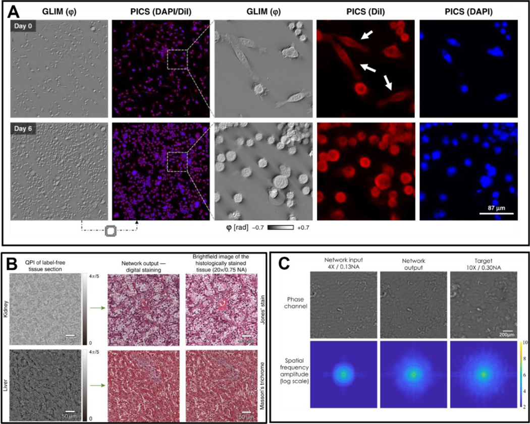
Figure 12.
Current trends in QPI. A.
Phase imaging with computational specificity (PICS)-To demonstrate time-lapse imaging and high-content screening capabilities, authors seeded a multiwell with three distinct concentrations of SW cells...

Figure 13.
Importance of protein-protein interactions and their relationship to polarizability and mass.
Counter-clockwise from top left: oligomerisation, antibody-antigen interactions, protein stability, viral infection, protein synthesis, G-protein coupled receptor signalling.

Figure 14.
Future challenges of light scattering-based microscopy.
A , Detector improvement for lowering shot noise B , Amplification of light scattering. C , Prolonged, repeated observation. D , Larger field of view for improved statistics. E , Improving measurement...

Figure 15.
Coherent brightfield (COBRI) microscopy.
(a) Schematic of the simplest configuration of COBRI microscopy with a stationary widefield illumination. (b) Schematic of COBRI microscopy with beam-scanning unit and contrast-enhancement unit. (c) C...

Figure 16.
Ultrahigh-speed 3D tracking of a single vaccinia virus particle on the surface of a live cell by COBRI microscopy.
(a) COBRI image of single vaccinia virus particles. (b) Estimation and removal of cell background enables background-free imaging of the virus particle. (c) Localization precision of a single virus pa...

Figure 17.
Experimental setups and mechanism for interferometric plasmonic microscopy (A-E) and plasmon-enhanced ptychography (F-G).
(A) Schematic showing the interferometric plasmonic microscopy (iPM) setup. (B) iPM real-space image showing a 40 nm Ag nanoparticle and (C) in reciprocal space. (E) Diagram showing incident angle ( u...

Figure 18.
Plasmon-enhanced images of ocular nerve tissue and simulated amplitude and phase contrast predicted for different thicknesses of carbon.
(A) Ptychography without plasmon enhancement and (B) PE-ptychography. The graphs represent line outs through the same 70 nm thick edge feature on the histological tissue section, with significantly en...

Figure 19.
Schematic illustration of the machine learning framework.
Reprinted (adapted) with permission from ref[ 398 ]. Copyright 2017 American Chemical Society.

Figure 20.
A) Block diagram of the CIDS scanning microscope. The red and green arrows correspond to the transmitted polarimetric and to the reflected fluorescence path, respectively[ 420 ]. B) An example of theo...

Figure 21.
Principles of label-free quantitative imaging with super-resolution by off-axis holography.
(a) Regular off-axis holography. (b) Multiplexing two wave fronts into a single hologram. (c) Multiplexing six wave fronts into a single hologram.

Figure 22:
Optical Transfer Function (OTF) for various configurations in transmission TDM. (a): digital holographic microscopy: the OTF depicts a cap of sphere with large lateral, but limited longitudinal extens...

Figure 23.
Schematic illustrations of scanning near-field optical microscope (SNOM).
(a) The original proposal of aperture-type SNOM (a-SNOM) by Edward H. Synge. The nanoscale orifice can convert localized near field into propagating far-field wave. (b) The original proposal of scatte...

Figure 24.
Pathways en route to broadband and multimodal SNOM for quantitative nano-imaging and nano-spectroscopy.

Figure 25.
Concept and spatial resolution characterization of IR photothermal imaging.
(A) Visible beam propagation geometry when the IR beam is off. (B) When the IR light is on, the photothermal effect leads to deflection of the visible beam. (C) IR photothermal imaging of a 500-nm pol...

Figure 26.
Widefield IR photothermal imaging setup and live-cell chemical maps.
(A) Mid-IR pump and visible probe are loosely focused to the sample and thus enables the widefield detection of the photothermal responses. (B-C) Label-free live ovarian cancer cell imaging targeted a...

Figure 27.
Energy level diagrams of pump-probe microscopy based on contrast mechanisms of
(a) ground state depletion, (b) stimulated emission, (c) excited state absorption, and (d) two-photon absorption.

Figure 28.
(a) Example of a two-beam laser-scanning pump-probe nanoscope setup. BS: beam splitter, EOM: an electro-optical modulator for intensity modulation, vpp: vortex phase plate, DM: dichroic mirror, PBS: p...

Figure 29.
Examples of label-free super-resolution Raman imaging.
A mouse brain tissue observed by a) conventional line illumination and b) structured line illumination Raman microscopy using 532 nm excitation. Raman peaks at 1682 cm u22121 (amide-I, red) and 2848 c...

Figure 30.
Illustration of the operation principle for the two possible directions:
(a). A narrow pump Gaussian beam at 532 nm, creates a hole in the middle of a wider IR probe beam. (b). Donut shape 532 nm pump beam blocks the periphery of the Gaussian IR probe beam and transmits on...

Figure 31.
The dip generated in the Gaussian IR probe beam was induced by the green pump beam. One diffraction limit unit is 600 u03bc m . (a). The image of the transmitted Gaussian probe beam and its profile. (...

Figure 32.
Gaussian probe IR laser beam at the diffraction limit scan across a resolution target containing 3-bars having a period of 500 u03bc m : (a). Without applying the pump beam. No resolution improvement ...

Figure 33.
Optical nonlinearity and super-resolution imaging in plasmonic NS.
(a)(d)(g) are various types of nonlinearities, including sub-linearity (a), super-linearity (d), and all-optical switch (g), from a single gold nanosphere (80- or 100-nm diameter). (b)(e)(h) Super-res...

Figure 34.
Optical nonlinearity and super-resolution imaging in dielectric NSs.
(a)(d)(g) are various types of nonlinearities, including sub-linearity (a), super-linearity (d), and all-optical switch (g), from a single silicon NS or silicon NS array. (b)(e)(h) Super-resolution sc...

Figure 35.
(Left) The essentials of NPMR. A train of intensity modulated pump pulses (red) is focused on a sample. Focused and position overlapping train of probe pulses (green), with constant intensity, are del...

Figure 36
A schematic view of the experimental system. The role of the galvo mirror is to enable the combination of SPOM and NMPR.

Figure 37.
(Left) Super resolution Photo-modulated reflectivity using single color or two color. The sample consists of Au double lines, 125 nm wide, with gaps of 370, 270 and 180 nm, respectively. (a) Line imag...

Figure 38.
Schematic for nonlinear structured illumination-based super-resolution microscopy. By spatially modulating the incident/excitation fields, one can detect higher spatial frequencies associated with the...

Figure 39.
Label-free tissue imaging with non-linear optical microscopy modalities. a) TPEF+SHG and b) H&E images of murine colon. The TPEF+SHG image (green:TPEF, red:SHG) was collected ex vivo through an endomi...

Figure 40.
When a glycerin microdroplet is illuminated near its edge with a tapered fiber tip, an image of the tip may be seen at the opposite edge of the microdroplet.

Figure 41.
Numerical simulations of image magnification ( M = R 1 / R 2 = 2 ) using a compound inverted Eaton lens.

Figure 42.
Numerical modeling of excitation and scattering of surface electromagnetic waves in a gradient waveguide made of doped graphite at u03bb 0 = 275 nm . The guided UV field propagating through the wavegu...

Figure 43:
Wave propagation on the surface of a sphere.
The wave is emitted from a point source at some point on the surface. While propagating, the wave initially expands but then focuses on the point antipodal to the source. If the wave gets absorbed at ...

Figure 44:
Stereographic projection. In the stereographic projection, a line is drawn from the North Pole of the sphere to the point to be projected. Where this line intersects the plane through the Equator lies...

Figure45 u2013
Microsphere nanoscopy.
(a) Contact mode setup and imaging examples (50u2013100 nm samples) (b) Resolution analysis by the PSF convolution method ( u03bb = 405 , confocal mode). (c) Non-contact scanning superlens imaging, se...

Figure 46
Metamaterial Solid immersion Lens (mSIL).
(a) Concept of mSIL and synthesis approach (b) Near-field coupling between nanoparticles in mSIL transforms incident propagating wave into large-area structured evanescent wave illumination of substra...

Figure 47:
Schematic of MSI in the transmission geometry.
(b) Virtual image of a dipole marked by the dot near the microsphere. The image intensity is plotted as a function of the transverse coordinate y and position x of the focal plane of the objective. Th...

Figure 48:
Imaging of subwavelength current distribution ( Equation (28) ).
(a) Scattered energy W (normalized to some W 0 ) towards the objective ( u2212 u03c0 / 2 < u03c6 < u03c0 / 2 ) as a function of the phase index of the current for several values of the particle siz...

FIGURE 49.
Designs of cellphone microscopy based on: (a) lensless shadow imaging on top of the sensor array, (b) digital in-line holographic imaging, (c) combination with the microscope objective, and (d) microo...

FIGURE 50.
(a) Comparison of images of various biomedical samples taken by a standard microscope with 10 u00d7 ( NA = 0.25 ) objective (left column) and by proposed cellphone microscopy (right column) through LA...

Figure 51.
Normally polarized dipole p creates an axially symmetric wave beam qualitatively described by the laws of geometrical optics. (a) u2013 Non-divergent beam and its normalized intensity distribution ove...

Figure 52.
Two normally oriented dipoles are resolved despite of the subwavelength gap u03b4.
The resolution occurs because the gap between two virtual sources is magnified so that u03b4 v > u03bb/2. The lens grants an additional magnification (u0394 > u03b4 v ). (a) A beam of parallel rays tr...

Figure 53.
(a) Intensity color map for two horizontal dipoles symmetrically sandwiched between a large silicon block and a 2D u00abmicrosphereu00bb of glass and separated by the subwavelength gap u03b4. The seco...

Figure 54
(a) Surface topography reconstructions of a 200-nm-groove standard and (b) Layout of compensated microsphere-assisted interference microscope. LS, light source. MO, microscope objective. MS, microsphe...

Figure 55
Real part of the electric field showing the evanescent wave coupling by a 4-u03bcm-diameter microsphere ( n sph = 1.5 ) . The evanescent wave was generated by total internal reflexion using at a subst...

Figure 56.
Arrays of sup-hemispheres. CSEM, Switzerland.[ 803 ]
Figure images are served from the NIH/NLM PubMed Central Open Access Subset or Europe PMC; copyright remains with the publishers and authors.
💬 Discussion
0 commentsNo comments yet. Be the first to start a discussion!
Leave a Comment