Abstract
Abstract The nuclear lamina—a meshwork of intermediate filaments termed lamins—is primarily responsible for the mechanical stability of the nucleus in multicellular organisms. However, structural-mechanical characterization of lamin filaments assembled in situ remains elusive. Here, we apply an integrative approach combining atomic force microscopy, cryo-electron tomography, network analysis, and molecular dynamics simulations to directly measure the mechanical response of single lamin filaments in three-dimensional meshwork. Endogenous lamin filaments portray non-Hookean behavior – they deform reversibly at a few hundred picoNewtons and stiffen at nanoNewton forces. The filaments are extensible, strong and tough similar to natural silk and superior to the synthetic polymer Kevlar ® . Graph theory analysis shows that the lamin meshwork is not a random arrangement of filaments but exhibits small-world properties. Our results suggest that lamin filaments arrange to form an emergent meshwork whose topology dictates the mechanical properties of individual filaments. The quantitative insights imply a role of meshwork topology in laminopathies.
🔬 Techniques
🧬 Organisms
✨ Fluorophores
🧪 Sample Preparation
🔬 Cell Lines
🏭 Microscope Brands
🧪 Reagent Suppliers
💻 Software Details
💾 Data Repositories
🏛️ Research Organizations (ROR)
Affiliated research institutions:
📋 Methods
Xenopus laevis nuclear lamina preparation for AFM measurements
X. laevis oocytes at stage VI were allowed to swell in a low-salt buffer (LSB) (10 mM HEPES, 1 mM KCl, 1 mM MgCl 2 , pH 7.4) for 20–25 min. A prick with a sharp needle punctured the oocyte and enabled the nucleus to slowly squeeze out. The intact nuclei were immediately transferred to Modified Barth’s Buffer (MBB) (7.5 mM HEPES, 88 mM NaCl, 1 mM KCl, 0.4 mM CaCl 2 , 0.8 mM MgSO 4 , 2.5 mM NaHCO 3 , 2 mM Ca(NO 3 ) 2 , TRIS to pH 7.5) and washed gently by a stream of the surrounding buffer repeatedly. The nuclei were then transferred to another Petri dish (World Precision Instruments) coated with poly- l -lysine (1 mg mL −1 ) which enabled the nuclei to stick firmly onto the glass surface of the dish. With a glass microneedle the nucleus was slightly pushed onto the surface while rolling the needle to break open the nuclear membrane such that the nucleoplasmic side was facing upward, i.e., INM. The nuclear contents including chromatin were gently removed and the stuck nuclear membrane washed with an ample volume of MBB (10–15 mL). If the ONM, i.e., the cytoplasmic side, were facing upward, we would not expect to see lamin filaments but only NPCs when imaged by AFM 87 . For the experiment with Benzonase ® nuclease (Merck), the open nuclear membrane was incubated with 2500 U mL −1 of the nuclease for 1–2 h at room temperature.
HeLa and MEFs nuclear lamina preparation
Nuclear lamina of HeLa Kyoto and MEF cells were prepared for imaging with AFM by de-roofing the nuclei. Cells were seeded on autoclaved coverslips (#1 or 1.5, Carl Roth) and allowed to grow at 37 °C (5% v/v CO 2 ) until a confluency of 75–90 % was obtained. The cells were prepared by washing the coverslips first with Ringer’s solution (+2 mM CaCl 2 ) followed by Ringer’s solution without CaCl 2 . The coverslips were then exposed to hypotonic Ringer’s solution (one part of calcium-free Ringer’s solution was diluted in two parts deionized water) to swell the cells and facilitate easy opening 88 . To open the nuclei, a two-step procedure was developed. In the first step, cells were opened by placing an Alcian blue-coated coverslip on the cell-coated coverslip for ~1 min. After ~30 s, the excess buffer between the coverslips was wicked using a filter paper. After a further ~30 s, the coverslips were separated by a stream of phosphate-buffered saline (PBS, pH 7.4) (500–1000 μL) using a pipette. This facilitated the transfer of half-open cells with intact nuclei onto the top coverslip (Alcian blue-coated). The coverslips were then transferred to deionized water to swell the nuclei. The nuclei were then treated with Benzonase ® nuclease (Merck) in PBS (supplemented with 2 mM Mg 2+ ) to digest the chromatin, washed with a high-salt buffer (PBS with 300 mM NaCl, pH 7.4), and then re-equilibrated in PBS. In the second step, the nuclei were opened to expose the lamina. For this, again an Alcian blue-coated coverslip was placed on the coverslip with nuclei, the excess buffer removed using a filter paper, and the coverslips separated by a stream of paraformaldehyde (4%) or PBS for experiments with unfixed nuclei. Both the coverslips were screened for nucleus and the one with higher density used for imaging. The procedure was carried out with and without protease inhibitors (Merck) without any noticeable effect on the lamin meshwork.
Show full methods section
Xenopus laevis nuclear lamina preparation for AFM measurements
X. laevis oocytes at stage VI were allowed to swell in a low-salt buffer (LSB) (10 mM HEPES, 1 mM KCl, 1 mM MgCl 2 , pH 7.4) for 20–25 min. A prick with a sharp needle punctured the oocyte and enabled the nucleus to slowly squeeze out. The intact nuclei were immediately transferred to Modified Barth’s Buffer (MBB) (7.5 mM HEPES, 88 mM NaCl, 1 mM KCl, 0.4 mM CaCl 2 , 0.8 mM MgSO 4 , 2.5 mM NaHCO 3 , 2 mM Ca(NO 3 ) 2 , TRIS to pH 7.5) and washed gently by a stream of the surrounding buffer repeatedly. The nuclei were then transferred to another Petri dish (World Precision Instruments) coated with poly- l -lysine (1 mg mL −1 ) which enabled the nuclei to stick firmly onto the glass surface of the dish. With a glass microneedle the nucleus was slightly pushed onto the surface while rolling the needle to break open the nuclear membrane such that the nucleoplasmic side was facing upward, i.e., INM. The nuclear contents including chromatin were gently removed and the stuck nuclear membrane washed with an ample volume of MBB (10–15 mL). If the ONM, i.e., the cytoplasmic side, were facing upward, we would not expect to see lamin filaments but only NPCs when imaged by AFM 87 . For the experiment with Benzonase ® nuclease (Merck), the open nuclear membrane was incubated with 2500 U mL −1 of the nuclease for 1–2 h at room temperature.
HeLa and MEFs nuclear lamina preparation
Nuclear lamina of HeLa Kyoto and MEF cells were prepared for imaging with AFM by de-roofing the nuclei. Cells were seeded on autoclaved coverslips (#1 or 1.5, Carl Roth) and allowed to grow at 37 °C (5% v/v CO 2 ) until a confluency of 75–90 % was obtained. The cells were prepared by washing the coverslips first with Ringer’s solution (+2 mM CaCl 2 ) followed by Ringer’s solution without CaCl 2 . The coverslips were then exposed to hypotonic Ringer’s solution (one part of calcium-free Ringer’s solution was diluted in two parts deionized water) to swell the cells and facilitate easy opening 88 . To open the nuclei, a two-step procedure was developed. In the first step, cells were opened by placing an Alcian blue-coated coverslip on the cell-coated coverslip for ~1 min. After ~30 s, the excess buffer between the coverslips was wicked using a filter paper. After a further ~30 s, the coverslips were separated by a stream of phosphate-buffered saline (PBS, pH 7.4) (500–1000 μL) using a pipette. This facilitated the transfer of half-open cells with intact nuclei onto the top coverslip (Alcian blue-coated). The coverslips were then transferred to deionized water to swell the nuclei. The nuclei were then treated with Benzonase ® nuclease (Merck) in PBS (supplemented with 2 mM Mg 2+ ) to digest the chromatin, washed with a high-salt buffer (PBS with 300 mM NaCl, pH 7.4), and then re-equilibrated in PBS. In the second step, the nuclei were opened to expose the lamina. For this, again an Alcian blue-coated coverslip was placed on the coverslip with nuclei, the excess buffer removed using a filter paper, and the coverslips separated by a stream of paraformaldehyde (4%) or PBS for experiments with unfixed nuclei. Both the coverslips were screened for nucleus and the one with higher density used for imaging. The procedure was carried out with and without protease inhibitors (Merck) without any noticeable effect on the lamin meshwork.
AFM imaging and force spectroscopy
As explained above, oocyte nuclei were attached onto poly- l -lysine-coated glass and were mechanically opened to ensure that the nucleoplasmic side was facing up, i.e., accessible to the AFM cantilever (Fig. 1a, b ) 87 . If the spread nuclear membrane folded (this happened usually at the edges because it could not stick to the poly- l -lysine surface), the sample was not measured in those regions. Since we always imaged and did our measurements in the center of the membrane, we are certain that all our measurements were conducted on the INM. In the AFM images of the lamin meshwork we took before pushing on the filament, no ruffles were observed. Moreover, folds and ruffles in the nuclear membrane can break the lamin meshwork. Uncoated cantilevers of nominal tip radius ≈10 nm (HQ:CSC38/noAl, MikroMasch, Europe) were used for imaging and force spectroscopy. Before imaging and force spectroscopy, the cantilever sensitivity was determined by pressing the cantilever on a clean part (uncoated) of the glass surface. The spring constants measured using the in-built calibration module of the AFM (Nanowizard III, JPK instruments, Berlin) agreed with the typical range of the nominal spring constant of 0.03–0.13 N m −1 . X. laevis oocyte nuclear lamina was imaged using AFM quantitative force imaging at 128 × 128 or 256 × 256 pixels. Random positions on lamin filaments were chosen in the closed-loop mode (feedback on); this is an entirely software-based “select and click” process that puts a cross-hair on the filament. Upon switching to the “force-spectroscopy” mode in the software, the tip of the AFM cantilever was pushed on the selected positions with a force of 8–10 nN at different velocities (0.05–5 μm s −1 ). AFM experiments were performed in an acoustically isolated, temperature-controlled enclosure (26 ± 1 °C). Importantly, the data were collected over a span of >2 years providing reproducible results ensuring that the quality and the selection procedure of the oocytes were maintained and did not affect the final results. The FE signals were exported in ASCII format from the JPK analysis software (v 4.2). The parameters: step unit (distance between the peak and the linear drop in the peak), failure force (peak of the force signal), stiffness (slope of the linear steep increase in the force signal), and deformation (distance between the inflection in the FE signal and the first force peak) were all determined manually using Punias 3D (v 1.0, Release 2.2) 89 . Specifically, the stifness before failure and after α-helix transition to β-sheet was determined by fitting a linear function to the relevant region of the curve—at the region prior to the peak occurrence (failure). The goodness of fit was estimated by the R 2 values (0.93–0.99) (Supplementary Fig. 9 ). More than 50% of the data was analyzed three times to ensure reproducibility of the analysis procedure. The results were always in agreement within
📊 Figures
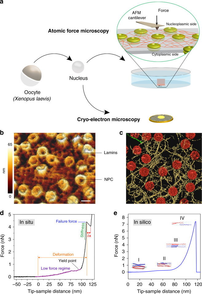
Fig. 1
Revealing the structural mechanics of in situ-assembled lamin filaments.
a A schematic illustration of the experimental set-up. Isolated nuclei from X. laevis oocytes were attached onto a poly- l -lysine-coated glass dish or carbon-coated electron microscopy grid. Next, th...
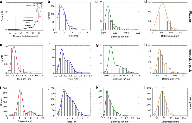
Fig. 2
Mechanical characteristics of lamin filaments.
a An FE curve showing a characteristic plateau and an intermediate peak preceding the final peak at high force (u22483u2009nN). b The plateau occurred at a force of 0.30u2009u00b1u20090.20u2009nN (ave...
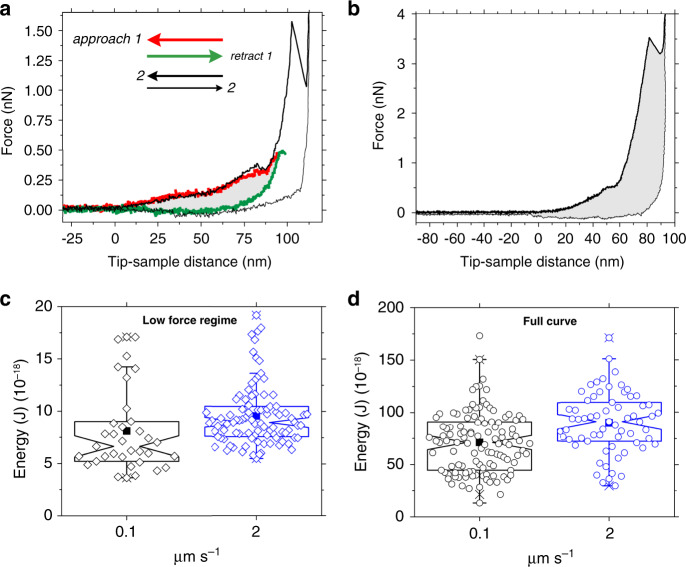
Fig. 3
Lamin filaments absorb energy under continuous applied force.
a To estimate the energy absorbed during the initial stretching of a lamin filamentu00a0(low-force regime), a repetitive force protocol was used. A force of 0.5u2009nN was applied (approach, red curve...
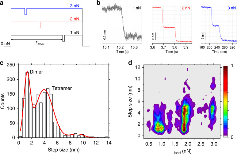
Fig. 4
Discrete failure steps of lamin filaments at constant loads (force clamp).
a Lamin filaments were subjected to constant loads ( F load ) ranging from 0.75 to 3u2009nN. The valleys denote a drop in force at break events. u03c4 break denotes the lifetime of a filament at a cer...
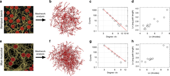
Fig. 5
Nuclear lamin meshworks of X. leavis oocyteu00a0and mouse embryonic fibroblast show similar topology.
The 3D lamin meshworks as viewed by cryo-ET of a X. laevis oocyte NE ( n =u200913 tomograms) (field of view, 700u2009nmu2009u00d7u2009700u2009nm) (Fig. 1b ) and e MEF NE ( n =u200912 tomograms) (adapt...
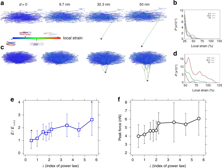
Fig. 6
Meshwork topology ( u03bb ) influences toughness and strength of lamin filaments.
Snapshots from simulations of mechanical pushing of single lamin filaments in meshworks of two different node connectivities: a u03bb =u20090.5 (Supplementary Movie 1 ) and c u03bb =u20095.6 (Suppleme...
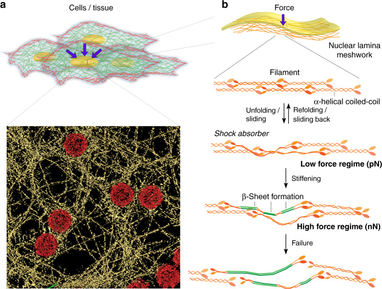
Fig. 7
Nuclear lamins under external forces.
a The cell nucleus is under constant stress from its surroundings and experiences continuous or prolonged mechanical shocks during division and migration 93 , 94 . The nuclear lamina forms a meshwork ...
Figure images are served from the NIH/NLM PubMed Central Open Access Subset or Europe PMC; copyright remains with the publishers and authors.
💬 Discussion
0 commentsNo comments yet. Be the first to start a discussion!
Leave a Comment